- Product Description
- Product Highlights
- Contact Information
- New Features
- Defects Fixed
- Documentation
- Contents of Release
- Platforms Supported
Product Description
Product Highlights
New Features in CUBIT™ 16.10
Index of New Features
- Robustness and speed improvements to node equivalencing
- Element area and length metrics now correct for all higher-order elements
- New expanded Sculpt command
- Scaling options in Sculpt
- Compressing material IDs from SPN files in Sculpt
- Improved handling of Stitch format in Sculpt
- Default processors in Sculpt command line
- New reduce surface slot command
- New blunt tangency command
- Additional SGM support in Cubit
- Fix for STEP import of multi-surface sheet bodies
- Classification of surfaces using machine learning
- Reinforcement learning for thin volume reduction
- Webcut solutions in meshing power tool
- New shell model management with the geometry power tool
- Geometry power tool new surface classification diagnostic
- Geometry power tool new slot surfaces diagnostic
- New reduce thin volumes with reinforcement learning command panel
- New reduce surface slot command panel
- New Sculpt command panels
- Python 3.6 through Python 3.11 now supported
- element_count extended parsing now supports exodus entities
- Tet meshing errors now correct
- CUBIT™’s python interface enhancements
- Cubit Bugs Fixes and Enhancements
Meshing
Robustness and speed improvements to node equivalencing
Element area and length metrics now correct for all higher-order elements
New expanded Sculpt command
Scaling options in Sculpt
Compressing material IDs from SPN files in Sculpt
Improved handling of Stitch format in Sculpt
Default processors in Sculpt command line
Geometry
New reduce surface slot command
New blunt tangency command

Additional SGM support in Cubit
- Names can now be assigned, removed, and renamed for SGM geometry entities.
- SGM geometry can be exported as either an SGM file or a STEP file.
- The “
Measure Between” command now supports measuring with SGM geometry entities.
- Importing with SGM provides powerful geometry healing, after which the healed geometry can be exported to a STEP or SGM file for subsequent use in Cubit, Morph, or other programs. Names can optionally be assigned to SGM entities, and the names will be written to the STEP or SGM file.
- SGM geometry can be imported along with free mesh for visualization and to measure distances between mesh and geometry.
Fix for STEP import of multi-surface sheet bodies
Classification of surfaces using machine learning
For more information see: ML Part Classification
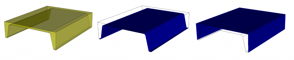
Reinforcement learning for thin volume reduction
Cubit now introduces a new feature, Reduce Thin Volumes with Reinforcement Learning. The RL option simplifies a 3D thin volume into connected sheet bodies, similar to the Reduce Thin Volumes Auto. However, instead of relying on a set of pre-defined rules, the RL option uses machine learning techniques to make predictions based on a persistent knowledge base. With each iteration, the method builds training data and improves its choices for reduce operations.
The RL option generates a sequence of Cubit commands that can be exported to a journal file for the user to validate, edit and archive. The resulting sheet bodies are automatically associated with the original 3D geometry and have attributes necessary for shell finite element analysis.
The RL tool operates in two modes: Predict Mode and Learning Mode. In Predict Mode, the method predicts the reduction operations based on established training data. In Learning Mode, the method gathers information about the state space of the assembly to establish training data. The method will stop based on a stopping criteria, reaching the maximum number of iterations, finding no additional unique solutions, or user abort. The user can also influence the learning process by adding their own training data through the Thin Volumes diagnostic in the Cubit Geometry Power Tool.
For more information see: Reduce Thin Volumes with Reinforcement Learning
Graphical User Interface
Webcut solutions in meshing power tool
Introducing a new addition to the Meshing Power Tool – a solutions window that displays potential webcuts for the selected volume. With a similar layout to the Geometry Power Tool, you can preview the webcut, and with a right-click on the displayed solutions, access a menu option that brings up the relevant webcut command panel, pre-populated with the necessary parameters. To activate the solutions window, simply check the “Show Webcut Solutions” checkbox at the top of the Meshing Power Tool.
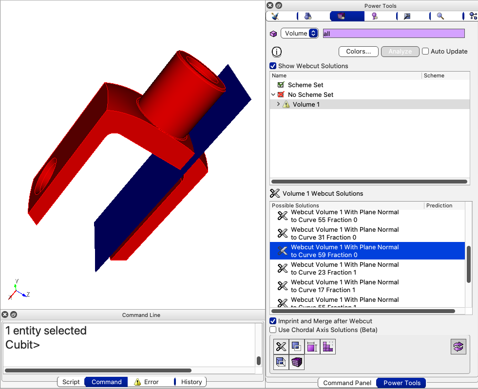
For more information see: Meshing Tools
New shell model management with the geometry power tool
Cubit’s Geometry Power Tool has been enhanced with the new Beam and Shell diagnostic, making it easier to simplify thin volume assemblies. This diagnostic streamlines the reduction of volumes to connected sheet bodies, which can then be meshed with triangles or quadrilaterals. When run with machine learning models loaded, the Analyze button produces two lists: Thin Volumes and Sheets. The Thin Volumes list offers custom reduction options, while the Sheets list displays defined sheet bodies with editable thickness, loft, and block attributes. The diagnostic also provides access to custom solutions for further customization and the option to export sheet data for analysis input deck setup. Additionally, quick access to automatic thin volume reduction tools, including reinforcement learning, is also available.
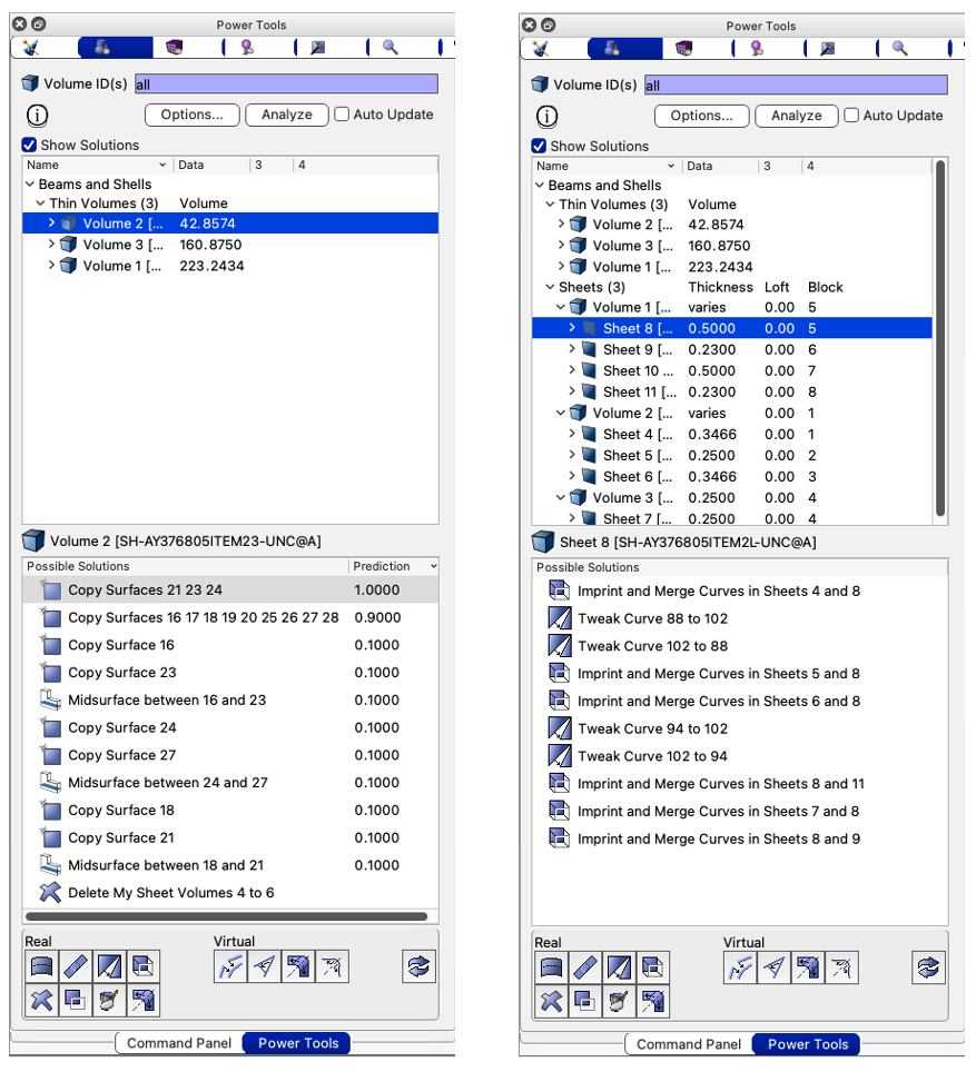
For more information see: Beams and Shells
Geometry power tool new classify surfaces diagnostic
A new diagnostic for surface classification has been added to the Geometry Power Tool. This diagnostic allows for classification of surfaces into custom categories, similar to the existing part classification feature. The classification is performed using machine learning models that can be loaded through the “Load ML Models” button in the Options panel. Upon analysis, each surface in the model will be assigned a predicted category.
For more information see: Machine Learning with Geometry Power Tool
Geometry power tool new slot surfaces diagnostic
The Slot Surfaces diagnostic is a new addition to the geometry power tool for preparing slot surfaces in Electromagnetic (EM) modeling. A slot surface is used to identify potential pathways where EM radiation can potentially exit. This diagnostic will help manage slot surfaces and prepare them for the application of boundary conditions and analysis. The diagnostic utilizes Machine Learning (ML) to predict the most likely slot surfaces. It also provides interactive tools for easily previewing and preparing slot surfaces for meshing using the external NGS Morph tool.
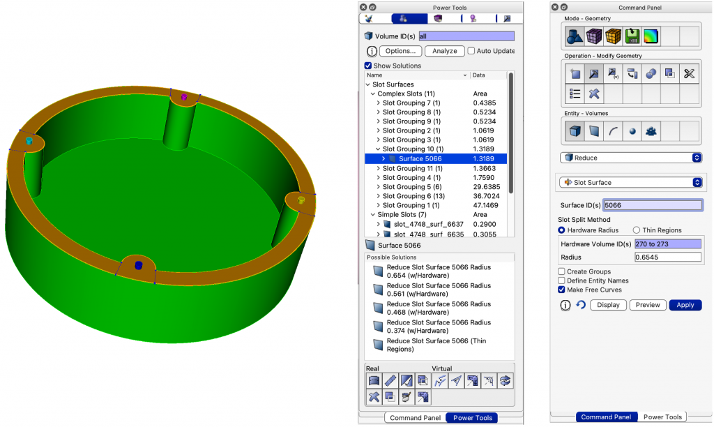
For more information see: Slot Surface Preparation, Reduce Slot Surface
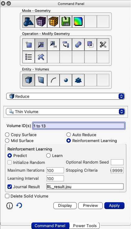
New reduce thin volumes with reinforcement learning command panel
The new “Reduce Volume Thin RL” command panel is a valuable addition to the suite of reduce operations that utilizes the latest in machine learning technology. This panel offers full access to the training and prediction of thin volume models using the new command line option for reducing thin volumes. When used in conjunction with the “Beams and Shells” diagnostic from the geometry power tool, the relevant volumes are automatically populated in the command panel, making it easily accessible from a context menu.
For more information see: Reduce Thin Volumes
New reduce surface slot command panel
The reduce surface slot command panel is a new addition to the suite of reduce operations that utilizes machine learning capabilities. When used in conjunction with the geometry power tool slot surfaces diagnostic, the slot decomposition process is made easier with the help of the new reduce surface slot panel. The panel provides options to input the hardware and radius information, automatically populating the necessary fields based on the slot geometry. Additionally, users have the ability to specify grouping and naming options for the decomposed slot surfaces.
For more information see: Reduce Slot Surface
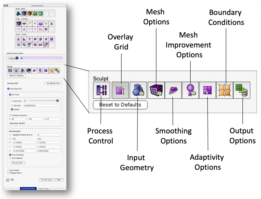
New Sculpt command panels
Cubit introduces new command panels for setting up Sculpt input, providing better support for the full range of Sculpt capabilities. The panels are organized based on the structure of the Sculpt input options and provide a comprehensive set of options that were previously only available when running Sculpt external to Cubit.
The new panels can be accessed from the Meshing->Volume->Sculpt menu and cover the following categories:
- Process Control: includes specifications for the number of processors, file names, and run options.
- Overlay Grid: allows you to set up either a Cartesian overlay grid or specify an Exodus mesh as the overlay grid. It also supports Pamgen overlay grids.
- Input Geometry: defines the geometry that will be used, with the default being the current geometry in Cubit. Alternative sources for geometry include external STL files, diatom files, volume fraction files, microstructure files, SPN files, or stitch files.
- Mesh Options: control the type of mesh including stair-step, mesh void, hex dominant, periodic and degenerate hexes.
- Smoothing Options: control options for smoothing curves and surfaces.
- Mesh Improvement Options: includes options for pillowing, defeaturing, geometry capture, thickening, and removing bad quality elements.
- Adaptivity Options: specify adaptive criteria, including the recent addition of adaptation based on material ID.
- Boundary Conditions: choose from several methods for generating sidesets, defining material and sideset names, and adding new boundary conditions.
- Output Options: set the output Exodus file name and define options for transformations, exporting various file types, and log output.
In addition, the Sculpt panel now includes a new Preview button that displays the contents of the Sculpt input file in the Cubit output window. This allows you to check the current structure of the commands and to copy and paste to a text file for running externally.
For more information see: Sculpt Commands
Miscellaneous
Python 3.6 through Python 3.11 now supported
Easier integration with user’s workflows, tools, and scripts is now enabled by supporting more than just Python 2.7 and 3.7. Cubit’s python modules can now be imported into any python environment of version 3.6 and newer. This is enabled by Cubit’s use of the Python Stable Application Binary Interface.
Element_count extended parsing now supports exodus entities
When using "element_count" in extended parsing, exodus entities are now supported. For example, the following command now works."list block with element_count > 2400"
Tet meshing errors now correct
The node ids generated when tetmeshing generated errors were previously incorrect. This has been corrected, allowing users to quickly locate areas in the triangle mesh that are preventing tetmeshing from succeeding.
CUBIT™’s Python Interface Enhancements
- gaps_between_volumes – Returns a list of VolumeGap objects defining the gaps
- is_surface_meshable – Returns whether a surface is meshable with the current scheme
- get_entity_names – Returns all names of an entity
Defects Fixed in CUBIT™ 16.10
| Ref# | Description |
| MESH-817 | Re-enable testing with graphics on the linux build machine. |
| MESH-4173 | keep_lower_geometry not recognized – remove option from GUI. |
| MESH-5135 | Refine in Sculpt based on geometry id. |
| MESH-6669 | Python 3.9+ compatibility. |
| MESH-6670 | Running sculpt 16.04 on a mac. |
| MESH-6680 | Open Command Panel if closed and power tool links hit. |
| MESH-6682 | SGM STEP import/export in CUBIT. |
| MESH-6695 | Incorrect journaled command. |
| MESH-6742 | Support multiple versions of python. |
| MESH-6749 | Investigate mesa issue on persistent DaaS machines. |
| MESH-6852 | Wrong node ids in tetmeshing error messages. |
| MESH-6877 | Rework genSlotModel with SGM and CUBIT. |
| MESH-6878 | Meshed surface area of tri6 incorrect. |
| MESH-6900 | Better handling of reversals in sweeping and interval matching. Using mesh angle for vertex type. |
| MESH-6909 | Long delays after Cubit unloads. |
| MESH-6911 | Parse_cubit_list error. |
| MESH-6948 | Column width option. |
| MESH-6951 | Undocumented command – Remove Sliver Curve. |
| MESH-6962 | Cubit 16.08 bug in gui model tree. |
| MESH-6972 | Tetmesh issue during training. |
| MESH-6975 | Sculpt version in cmake list. |
| MESH-7097 | Sculpt parallel command when hitting preview input. |
| MESH-7105 | Bug projecting then imprinting curves onto composite surface. |
| MESH-7107 | Super vs. Superelement_topology. |
| MESH-7118 | Support for element_count to use element blocks, sidesets and nodesets. |
| MESH-7119 | Simple volume should be automatically sweepable. |
| MESH-7121 | Fix recent regression in create curve polyline with locations. |
| MESH-7134 | Improvements in sweeping quality. |
Documentation Updates
The CUBIT™ 16.10 online documentation may be found here. A PDF version is also available for download. The CUBIT™ GUI installation also includes the full user documentation included with the program. The user’s manual may be accessed from the Help menu.
CUBIT™ 16.10 Contents of Release
CUBIT™ Program: The installation package includes executables and libraries, packaged in tar.gz files for Linux machines. For Windows, the package is in a self-installing executable, and for Mac OS X a .dmg file is provided. Both a command line and GUI version of CUBIT™ are included with the installation package for all platforms.
Documentation: Linux, Windows and Mac versions include full online documentation.
Platforms Supported
CUBIT™ 16.10 supports the following Platforms:
- Linux RedHat Enterprise 7 and 8
- Windows 10
- macOS 10.14+
Non-Sandia Users
CUBIT™ is freely available for United States government use. For more information on licensing CUBIT™, including academic, commercial, and all other use, go to our licensing page. For current CUBIT™ users, CUBIT™ 16.10 may be downloaded from the CUBIT™ download page.
Sandia Personnel Only
CUBIT™ 16.10 may be downloaded from the CUBIT™ download page.
Windows
Download a Windows installation file and double-click to install.
MAC OS X
Download a Mac OS X disk image file. After the disk image is opened, click and drag the CUBIT™ folder to /Applications.
LINUX LANS
Check with your local LAN administrator for instructions on how to access CUBIT™ on your local LAN. In most cases typing one of the following commands at the UNIX prompt should allow you to execute CUBIT™. In some cases, the full path will need to be specified:
/projects/cubit/<cubit_command>
| cubit | The latest released version (16.10) of CUBIT™ deployed to the LAN. |
| cubit -nogui | The latest released version (16.10) with just the Command Line and graphics window |
| cubit -nogui -nographics | The latest released version (16.10) with just the Command Line |
| cubit-16.10 | Version 16.10 with GUI |
| cubit-beta | The latest beta version still in development |
Contact Information
CUBIT™ Help
For general technical questions including download, installation and CUBIT™ technical assistance.
CUBIT™ Licensing and Passwords
Email: asc-approvals@sandia.gov
CUBIT™ Support Lead
Trevor Hensley
Phone: 505-284-7756
Email: cubit-help@sandia.gov
CUBIT™ Project Lead
Roshan Quadros
Sandia National Laboratories
Computational Simulation Infrastructure (org. 1543)
Phone: 505-220-9458
Email: wrquadr@sandia.gov