Cubit 16.10 User Documentation
The Reduce Thin Volumes commands simplifies a 3D thin volume into a connected set of sheet bodies. The reduce thin commands are frequently used with the intention of generating shell finite elements. Note that these commands will perform similar geometric operations to the surface copy and midsurface commands, but will also keep track of thickness and loft; attributes necessary for building a full representation for shell finite element analysis. The resulting sheet bodies will also automatically generate blocks with these attributes and will maintain their association to their original 3D parent geometry.
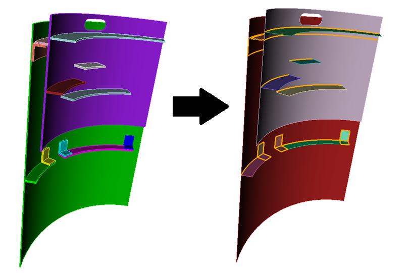
The Thin Auto version (illustrated in figure 1) automatically reduces a set of 3D thin volumes into a connected set of sheet bodies based on an internal geometric reasoning algorithm resulting in sheet bodies that are connected at shared (merged) curves. It will also automatically build thickness, loft and block information. The copy and midsurface versions of the command are more prescriptive, and offer more control so that specific required reductions can be performed. The copy option can be used to prescribe a few required reductions in an assembly prior to automatically reducing the remainder with the reduce thin auto command.
Figure 1. Reducing a set of 3D thin volumes. Merged curves are highlighed.
Syntax:
Reduce Volume <volume ids> Thin Auto [Sort] [Preview]
Reduce Volume <volume ids> Thin Copy <surface ids> loft factor <values> thickness <values>...[Combine] [Delete] [Preview]
Reduce Volume <volume id> Thin Midsurface surface <id1, id2> loft factor <value> thickness <value> [Combine] [Delete] [Preview]
Thin Auto
To use the Thin Auto command, the 3D thin volumes must be touching so that if the user imprinted and merged them, they would be connected at merged surfaces. This routine traverses the set of 3D volumes, finding the best 2D reductions that preserve connections between the 3D volumes. This routine also creates shell element blocks containing the resulting 2D shell surfaces. Each block also is attributed with appropriate thickness and loft factor values corresponding to the parent 3D volumes. These thickness and loft factor values are the first and second block attributes respectively. Finally the command creates an internal association between the original 3D parent volume and the 2D reduction so that the user is able to visually inspect and validate the reduction. See the draw shell volume command below for more details.
volume ids: Specify the ids of the 3D volumes to be reduced. These volumes should not already be imprinted and merged. However, users should be certain that the volumes do indeed imprint and merge successfully since the routine does this internally to ultimately connect the resulting 2D shell surfaces. If a user wants to prescribe a specific reduction solution, it can be done manually using the Reduce Thin Copy command. To include the manually reduced volumes in the auto operation, the parent 3D volumes (not the generated 2D reductions) should be specified along with the other 3D volumes being reduced.
sort: If the sort option is specified, the surfaces of all 2D reductions containing the same base name will be added to the same block. This is done so that copies of the same volume remain together. These volumes should be identical in nature, with the same thickness. For example, if the user has a repeated part in the model with the base name 'bracket', all 2D reductions with that base name, like 'bracket@A', 'bracket@B', 'bracket@C',... will have all their surfaces added to the same block. If the sort option is not used, the surfaces of each 2D reduction will be in their own block. In either case, the next available block id is used.
It is also important to note that only 3D thin volumes that have two logical sides can be automatically reduced. For example, a piece of sheet metal, bent or pressed into most shapes has two logical sides. 3D thin volumes with t-junctions do not have two logical sides. See figure 2 below for some examples.
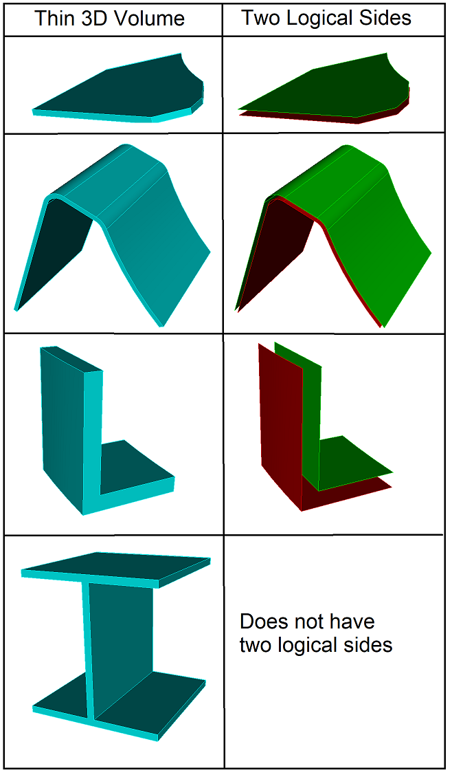
Figure 2. Logical sides of thin volumes.
Thin Copy and Midsurface
Using this form of the command, the user defines the reduction by specifying the surfaces the thin 3D volume will be reduced to. Unlike the auto form, nothing is done to make adjacent reductions contiguous. Each surface must be specified with a corresponding loft factor and thickness value. The combine option reduces a volume into a multi-surface sheet body. Otherwise, each surface will result in a single-surface sheet body. delete option deletes the original 3D thin volume(s).
Note that sheet bodies created using the \textbf{reduce thin midsurface} option, are currently not supported in the auto option. If the intention is to initially prescribe a few reductions prior to using the auto command, avoid using the midsurface command.
Draw Shell Volume
To visually inspect that the 2D reductions correctly approximate the original 3D thin volumes, the command below can be used. The 3D volume is drawn in wireframe mode, 2D reduction in shaded mode, and the element block of the 2D reduction in shaded or optionally transparent mode.
Draw Shell Volume <ids> [Color<color_spec>] [Transparent] [Add]
Exporting Shell Data
To export information to a csv file detailing the reductions, the command below can be used:
Export Shell Data <string> [Volume<ids>] [Brief] [Overwrite]
By default, the following columns are written for each 3D volume specified. If no volumes are specified, the data for all 3D thin volumes reduced are exported. For each 3D thin volume, the following columns of data are exported:
| sheet body ID | sheet body name | parent volume ID | parent volume name | thickness | loft | block |
If the brief option is used, only the following columns of data are exported:
| block | sheet base name | thickness | loft |