Cubit® is a full-featured software toolkit for robust generation of two- and three-dimensional finite element meshes (grids) and geometry preparation. Its main goal is to reduce the time to generate meshes, particularly large hex meshes of complicated, interlocking assemblies.
Product Highlights
Meshing: Cubit® is a solid-modeler based preprocessor that meshes volumes and surfaces for finite element analysis. Mesh generation algorithms include quadrilateral and triangular paving, 2D and 3D mapping, hex sweeping and multi-sweeping, tet meshing, and various special purpose primitives. Cubit® contains many algorithms for controlling and automating much of the meshing process, such as automatic scheme selection, interval matching, sweep grouping and sweep verification, and also includes state-of-the-art smoothing algorithms.
Geometry Preparation: One of Cubit®’s strengths is its ability to import and mesh geometry from a variety of CAD packages. Cubit® currently integrates the ACIS and Catia geometry kernels directly within its code base, allowing direct manipulation of the native CAD geometry format within Cubit®. This reduces the errors and anomalies so often associated with geometry translation. CGM (Common Geometry Module) also boasts a facet-based geometry kernel developed at Sandia that can be used for remeshing or editing old mesh files or models defined by triangle facets. In addition, Cubit® has developed a comprehensive virtual geometry capability that permits local composites and partitions to geometry without modifying the underlying native geometry representation. The user can choose to ignore, clean-up or add features to the model allowing greater flexibility to meshing algorithms to generate better quality elements.
Cubit® Environment: Cubit® has developed both a convenient command line interface with an extensive command language as well as a polished graphical user interface environment. The GUI is based upon the cross-platform standard Qt, which allows the same look and feel on all supported platforms. Also included is a graphical environment based upon the VTK graphics standard which has been optimized for display and manipulation of finite element data and geometry. Fast, interactive manipulation of the model is a tremendous advantage for models with thousands of parts or millions of elements.
For more information on Cubit®, including licensing arrangements and terms see the Cubit® website.
Enhancements reading nodal/element variables when importing Exodus files
CGNS export now available
CFD_BCs such as supersonicinflow and supersonicoutflow are added
Meshing
Mesh-based boundary conditions propagate with geometry copy
Element blocks, nodesets, and sidesets created from mesh (not geometry) are now copied when owning geometry is copied if the block/nodeset/sideset settings are active for copying. Previously, only boundary conditions containing geometry were propagated during a copy.
Element area and length metrics now correct for all higher-order elements
The element area and length quality metrics for 2D and 1D elements respectively did not previously consider the higher order nodes in the computation, as if the elements were linear. This has been corrected so that they are now considered.
Expect more robust triangle and tetrahedral meshing from an upgraded version of Meshgems.
Tet meshing can now consume specified hardpoints
When using the tetmesh respect capability to insert locations into a tet mesh, the given nodes are now consumed and used by the resulting tets. This also means the specified nodes are no longer duplicated. Using the original nodes is useful for being able to query tets related to the given nodes.
The reduce volume bolt patch command is used to simplify bolt fastenings between two or three volumes, creating sidesets that define contact regions. These sidesets are generated as circular patches, centered on the bolt axis, using a specified radius. Enhancements in this release encompass several new optional arguments and behaviors:
New Default Naming Convention:
Default Convention: Sidesets are now automatically named for clear identification, based on the parent volumes or blocks they connect. For example, sidesets between “PartA” and “PartB” will be named PartA_to_PartB_123 and PartB_to_PartA_123, incorporating the contacting parts’ names and an ID for the replaced volume’s bolt, such as _123.
Alternative Convention: By setting sideset_naming_convention 1, sidesets adopt a Bolt_Patch prefix, followed by_Lower or _Upper to denote their position relative to the bolt’s bearing surface, plus an integer for the bolt volume ID. Use this option for the alternative naming method. The default method (sideset_naming_convention 0) does not require specification.
Explicit Surface Identification: If Cubit® can’t auto-detect contact surfaces, you can specify them manually.
Radius Factor: New option to set the radius as a factor multiplied by the bolt shaft radius, or the hole radius if a bolt isn’t present.
Surface Patch Naming: The resulting circular surface patches can be named for easier referencing in later scripts or journal commands.
Incremental ID with Start ID: The increment ID feature now allows a separate starting ID, enabling the same patch to be added to multiple sidesets.
Robustness Improvements: Enhancements to handle cases where up to three volumes are fastened by the same fastener.
The full syntax for the reduce patch command is as follows:
The upper and lower surfaces of a blot hole can now be specified, instead of the bolt volume, to create spider joints. This can be helpful when bolts do not exist in the model but bolt holes do. Additionaly, new options have been added to place the upper and lower parts of the spider into separate blocks. The command now is this:
It composites the two surfaces created from the blunt tangency operation with the larger surrounding surface. This allows surface meshing to not be constrained by the extra geometry created from the blunt tangency operation.
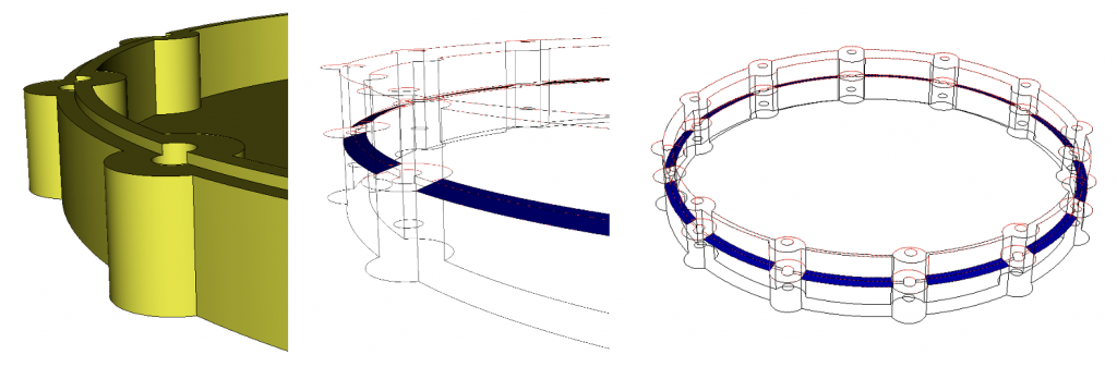
The Reduce Surface Slot command is a specialized tool developed to prepare models for electromagnetic (EM) simulations. It identifies and configures slots—pathways that permit EM radiation to traverse—by establishing clear inside and outside curve definitions, along with the pathways themselves. This command is integral to preparing models for the Morph tet meshing tool, ensuring that curves and surfaces are explicitly named for easy reference within the Morph input deck. New features include:
Explicit Curve Definition: Enables manual definition of inside and outside curves where automatic assumptions are inadequate, integrating seamlessly with Morph tet meshing tool inputs.
Hardware Independence: Automatically detects circular holes for fasteners, applying user-defined radii to delineate pathways, enhancing the command’s utility and flexibility.
Radius Parameter Expansion: Broadens radius definition options, including multiplicative factors and the Shigley angle for hardware-associated radii.
Boundary Snapping Tolerance: Improves tolerance to 10% of the radius size, reducing minor curve and tangency creation during slot surface division.
Create Skin Option: Facilitates sheet body generation for slot pathways, simplifying lofted surface creation between curves.
Preview Feature: Offers a visualization tool for better understanding of slot pathways in relation to the model, highlighting pathways in blue and the volume in wireframe.
Model showcasing the application of the Reduce Surface Slot command on multiple non-coplanar surfaces. Blue shaded areas indicate the preview of potential sheet bodies generated by the command.
The full syntax for the reduce surface slot command is as follows:
A new command has been added to create a cylinder fit to a volume:
[Create] Cylinder Volume
Creating a cylinder fit to a volume.
The input volume must have cylindrical or circular features that guide the definition of the “bounding” cylinder. The list volume geometry command will not recognize cylinder primitive volumes and list data to define the cylinder: RCC: followed by 7 doubles: X,Y,Z of bottom center; Dx,Dy,Dz from bottom center to top center; and radius. Similar data is listed for a brick primitive: BOX: followed by 12 doubles: X,Y,Z of first corner, and 3 sets of Dx,Dy,Dz for each adjacent corner.
Modified state now indicated in journal file editor
The user can now know if the contents of the journal editor are modified or if they are unmodified and reflect the content of a file on disk. An asterisk symbol now shows if the contents are modified. On the other hand, when saving the file or undoing changes, the asterisk symbols will disappear.
New Power Tools panel layout
The Power Tools panel has been reorganized to prioritize the enhanced Geometry Diagnostics tool as the initial tab, reflecting its increased utility and integration of features previously exclusive to the Wizard tool. While the Wizard remains accessible and useful, its position has been shifted to emphasize the updated capabilities and improvements within the Geometry and Meshing tools.
Reduce for Simulation and Fasteners: New ML Geometry Power Tool Diagnostics
The Geometry Power Tool now includes a Reduce for Simulation feature, available in the Options panel. Activate it by clicking the Load ML Tools button to import the machine learning models. This enhancement introduces a collection of ML-driven diagnostics within the Reduce for Simulation category, designed to streamline geometry for simulation. This update introduces a Fasteners category and reorganizes Slots and Beams and Shells into the newly established Reduce for Simulation diagnostic suite.
The Fasteners category, a new addition, enhances capabilities found in the Part Classification’s bolt section. It offers three bolt categorization methods:
Clamped Members: Groups bolts by the members they fasten.
All Bolts: Categorizes bolts by name, derived from step or ACIS file definitions.
Pilot Holes: Lists concentric hole pairs for potential fastener application, irrespective of existing fasteners.
Utilizing the Analyze button, Cubit employs machine learning to classify and categorize bolts and holes, offering individual or group operations. Additional features include visualization tools and context-sensitive solutions for bolt reduction, displayed in a secondary window for selected fasteners or pilot holes. Right-clicking enables custom simulation preparation options via the command panels.
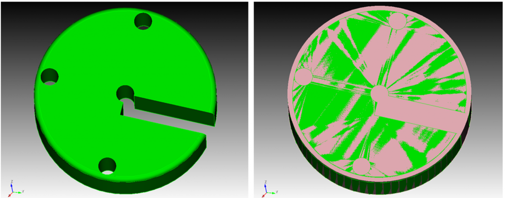
Below is an illustration of the Geometry Power Tool, showcasing the three categories and sample geometry with highlighted clamped members and associated bolts.
New Fasteners diagnostic shows clamped members with their associated bolts
When executing Python scripts in Cubit®, syntax errors now abort the processing of a script file or a set of statements. Similarly, a syntax error with a Cubit® command will abort the processing of a script file.
The exit code of Cubit® can indicate a failure with processing scripts. A Python exception will cause the exit code of Cubit® to be non-zero. If a script wants to specify the exit code for Cubit®, a sys.exit(<exit_code>) statement can be used.
Enhanced Python Interface for Bolt Analysis
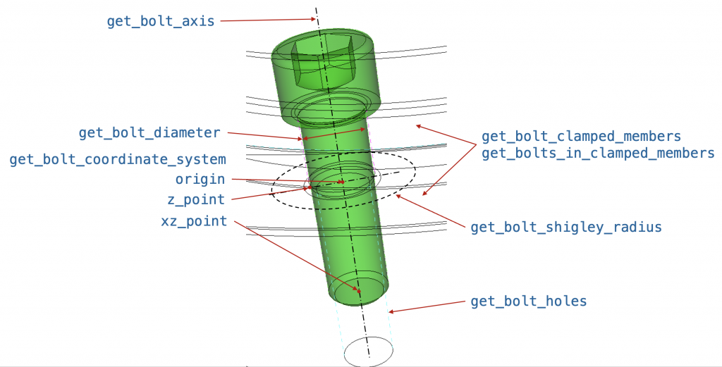
This Python interface provides advanced functionalities for analyzing bolts within a model, leveraging machine learning (ML) classifications to identify and interact with bolt features. It extends existing capabilities like get_bolt_diameter and get_bolt_axis with the following functions:
get_bolt_coordinate_system: Retrieves the necessary three coordinate locations (origin, z_point, and xz_point) to define a Cartesian coordinate system for a Sierra input deck. This aids in setting up simulation environments with precise bolt positioning.
get_bolts_in_clamped_members: When provided with two volume or block IDs, this function returns a list of volume IDs representing bolts that fasten the two members together. It utilizes ML classification to accurately identify the relevant bolts.
get_bolt_clamped_members: Given a bolt volume ID, this function identifies and returns the two members that are being clamped by the specified bolt, facilitating a clearer understanding of assembly and connection points within the model.
get_bolt_holes: Accepting two or more volume IDs, this function identifies potential pilot holes for fastener application, returning two lists of surfaces. The first list contains surfaces in the upper or bearing surface volume, while the second list includes surfaces in the lower or threaded volume. This distinction helps in utilizing the reduce surface hole command to define contact patches at holes.
The image below illustrates a bolt, highlighting the Python functions available for use and the specific geometric information each function returns.
Enhancements reading nodal/element variables when importing Exodus files
Element/nodal variable names can now be specified to import these variables. Additionally, all variables can be imported with the ‘all_nodal_vars’ and ‘all_element_vars’ options.
CFD_BCs such as supersonicinflow and supersonicoutflow are now supported
Users can specify CFD BCs on a region using the following command. The actual definition of the CFD BCs must be specified in the CFD solvers input deck. The full command is:
MESH-7726 Cubit 16.14 at AWE on Ubuntu workstation – start error and fix
MESH-7727 ‘individual’ option in ‘sweep surface’ command is not documented
MESH-7730 Cubit-beta doesn’t open
MESH-7731 Issues of spn to sculpt
MESH-7732 Increase code coverage in GeomMeasureTool
MESH-7741 AWE using Sculpt for microstructure problems.
MESH-7745 Collapse tri
MESH-7752 Cubit 16.14 cubit/python button to switch between python and commands
MESH-7753 Cubit doesn’t switch to python mode when you cut and paste?
MESH-7755 Model Tree not updating with journal file command line import with undo on
Documentation Updates
The Cubit® 16.16 online documentation may be found here. A PDF version is also available for download. The Cubit® GUI installation also includes the full user documentation included with the program. The user’s manual may be accessed from the Help menu.
Cubit® 16.16 Contents of Release
Cubit® Program: The installation package includes executables and libraries, packaged in tar.gz files for Linux machines. For Windows, the package is in a self-installing executable, and for macOS a .dmg file is provided. Both a command line and GUI version of Cubit® are included with the installation package for all platforms.
Documentation: Linux, Windows and Mac versions include full online documentation.
Platforms Supported
Cubit® 16.16 supports the following Platforms:
Linux RedHat Enterprise 7 and 8
Windows 10 and 11
macOS 10.14+
Non-Sandia Users
Cubit® is freely available for United States government use. For more information on licensing Cubit®, including academic, commercial, and all other use, go to our licensing page. For current Cubit® users, Cubit® 16.16 may be downloaded from the Cubit® download page.
Download a Windows installation file and double-click to install.
macOS
Download a macOS disk image file. After the disk image is opened, click and drag the Cubit® folder to /Applications.
Linux LANs
Check with your local LAN administrator for instructions on how to access Cubit® on your local LAN. In most cases typing one of the following commands at the UNIX prompt should allow you to execute Cubit®. In some cases, the full path will need to be specified:
/projects/cubit/<cubit_command>
cubit
The latest released version (16.16) of Cubit® deployed to the LAN.
cubit -nogui
The latest released version (16.16) with just the Command Line and graphics window
cubit -nogui -nographics
The latest released version (16.16) with just the Command Line
cubit-16.16
Version 16.16 with GUI
cubit-beta
The latest beta version still in development
Contact Information
Cubit® Help
For general technical questions including download, installation and Cubit® technical assistance.