Cubit 16.16 User Documentation
The Reduce Slot Surface is used to decompose slot surfaces in Electromagnetic (EM) modeling for easier application of boundary conditions.
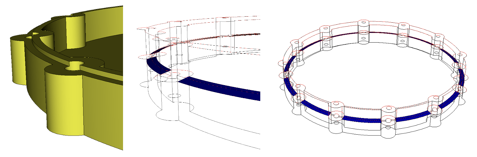
Figure 1.Example preview of slot surfaces, shown in blue (right) constructed from the original geometry (left).
Syntax:
Reduce Surface <ids> slot [inner {curve <ids>}] [outer {curve <ids>}] [hardware volume <ids>] [radius {<value>|Factor <value>|SHIGLEY [angle {<angle>}]}] [[create] skin] [group <string>] [group_edges <string>] [group_inner_edges <string>] [group_outer_edges <string>] [group_inner_surfaces <string>] [group_outer_surfaces <string>] [name <string>] [name_edges <string>] [name_inner_edges <string>] [name_outer_edges <string>][name_inner_surfaces <string>] [name_outer_surfaces <string>][make_free_curves] [preview]
Discussion:
The Reduce Surface Slot command is engineered for the preparation of models for electromagnetic (EM) simulations, facilitating the creation of slots—pathways allowing EM radiation to traverse. This command is versatile, designed for compatibility with both Cubit quad and tri meshers and the Morph mesher. It plays a vital role in generating surface meshes essential for EM simulations.
Prerequisites and Best Practices:
Before invoking the Reduce Surface Slot command, adhere to these best practices to ensure optimal model preparation:
Defeaturing and Simplification: Simplify the model by defeaturing or removing unnecessary details that may complicate splitting procedure in the reduce slot command.
Enclosure Integrity: Verify that the enclosure region is fully closed. Use the remove surface commands as necessary to seal any gaps or holes.
Imprint and Merge: For mismatched mating surfaces above and below the slot pathways, perform an imprint and merge operation to ensure that the upper and lower slot surfaces align perfectly.
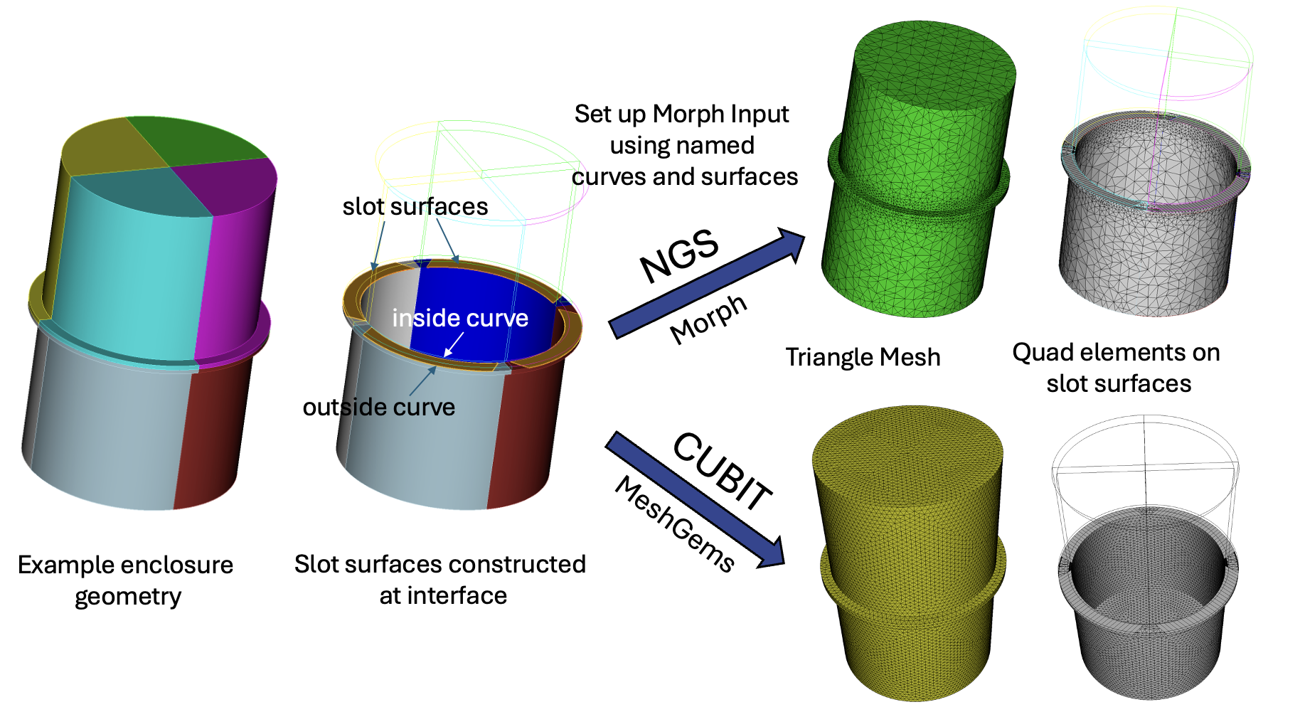
Figure 2.Slot Preparation Workflow: Identification and division of slot surfaces via the reduce surface slot command. The images display the distinct meshing results with Cubit or Morph.
Common Steps for Cubit and Morph Workflows:
Adjust Options: Customize the command settings according to the provided command syntax description.
Invoke the Command: Execute the Reduce Surface Slot command to begin the process of defining and splitting the slot surfaces. It's also worth noting that achieving the desired outcome may require some trial and error, with a preview option available to visualize the slot pathways before finalizing.
Cubit Workflow:
For Cubit, the focus is on direct mesh generation:
Mesh Preparation: Unlike Morph, Cubit does not require specific naming of surfaces and curves for mesh generation.
Quad Meshes on Slot Surfaces: Explicitly generate quad meshes on the slot surfaces using Cubit commands for assigning intervals, setting schemes and meshing.
Tri Meshes for Remaining Surfaces: Apply tri meshers for the rest of the model, setting mesh size, scheme, and then meshing directly in Cubit.
Morph Workflow:
For Morph, the emphasis is on preparing data for meshing in an external process:
Surface and Curve Naming: Important for Morph, where naming conventions are essential for the mesher to recognize and process the model correctly. Names can be explicitly identified in the command or the default naming convention may be used.
Export Patch Data: Utilize the export patch data command to provide Morph with the necessary information for quad and tri mesh generation.
Command Syntax Description:
The reduce surface slot command supports two distinct decomposition approaches: the Hardware Radius method and the Thin Regions method.
Hardware Radius Method: This approach mandates specifying a radius, which acts as the cutting parameter on the slot surface for each fastener or hole. When fastener volume IDs are supplied, decomposition centers around the fasteners' centroids at their intersection with the surface. In cases without specified hardware but with a defined radius, the method automatically identifies any holes, utilizing their centers as the foundation for radius application and subsequent cutting.
Thin Regions Method: This approach is designed to automatically identify and segment areas of constant thickness on the surface. It executes cuts at points where the surface width varies, providing an intuitive means of decomposition without requiring explicit hardware or radius inputs. The Thin Regions method is activated automatically in the absence of specified radius specification.
group: Used to create and name a group containing all resulting decomposed surfaces. The options group_edges, group_inner_edges, group_outer_edges, group_inner_surfaces and group_outer_surfaces are used to create and name groups of cutting curves, inner curves, and outer curves, respectively.
name: Similar to the group option, but individual names are assigned to the resulting decomposed surfaces and curves. The names of decomposed surfaces, side curves, inner curves, outer curves, inner surfaces and outer surfaces can be defined using the respective options. If not specified, a default naming convention will be used. Note that these names will be used in the Morph input deck and can be written using the export patch data command
make_free_curves: A specialized option to generate free curves at the boundaries of the decomposed slot surfaces. Grouping and naming options also apply to the free curves.
create skin: This function constructs a sheet body through a lofting process that spans from inner to outer curves. It is applicable to any slot surface, offering significant utility when dealing with multiple surfaces that do not form coplanar paths. This feature is particularly valuable for defining surfaces for quad meshing, effectively outlining the electromagnetic (EM) pathway.
preview: Displays a blue preview of the slot paths without performing the actual cutting operations as well as a wire frame outline of the owning volume