Cubit 16.16 User Documentation
The Reduce Bolt command generates a proxy representation of a bolt for analysis. It replaces the bolt geometry with two concentric circular surfaces centered on the bolt axis, separating the connected volumes where sidesets are automatically applied.
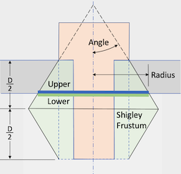
Figure 1. Example of the Reduce Bolt Patch command. The Shigley frustum is used to calculate the diameter of the sidesets positioned between the volumes.
Syntax:
Reduce {volume <ids>|upper surface <ids> lower surface <ids>} {bolt|hole} patch [contact upper {surface <ids>}] [contact lower {surface <ids>}] [radius {<value>|Factor <value>|SHIGLEY [angle {<value>}]}] [mesh] [mesh_size <value>] [mesh_scheme <string>] [no_simplify_hole] [{FILL|no_fill}] [{DELETE|no_delete}] [array_name <string>] [upper_patch_sideset_id {<value>|Default}] [increment_upper_patch_sideset_id] [start_upper_sideset_id {<value>|Default}] [upper_patch_sideset_name {<string>|Default}] [lower_patch_sideset_id {<value>|Default}] [increment_lower_patch_sideset_id] [start_lower_sideset_id {<value>|Default}] [lower_patch_sideset_name {<string>|Default}] [name_patch_surfaces] [preview]
Discussion:
The Reduce Bolt Patch command is often used in structural dynamic applications to replace bolts or bolt holes with concentric circular sidesets attached to the upper and lower volumes. If the specified radius exceeds surface bounds, clipping occurs. The resulting circular surfaces are automatically assigned to customizable sidesets. The patch radii are determined using the default Shigley frustum angle, as illustrated in Figure 1. Users can modify the Shigley angle or set the diameter explicitly as an absolute value or a factor of the shank radius. The command also supports automatic meshing of the sidesets with a user-defined scheme and size.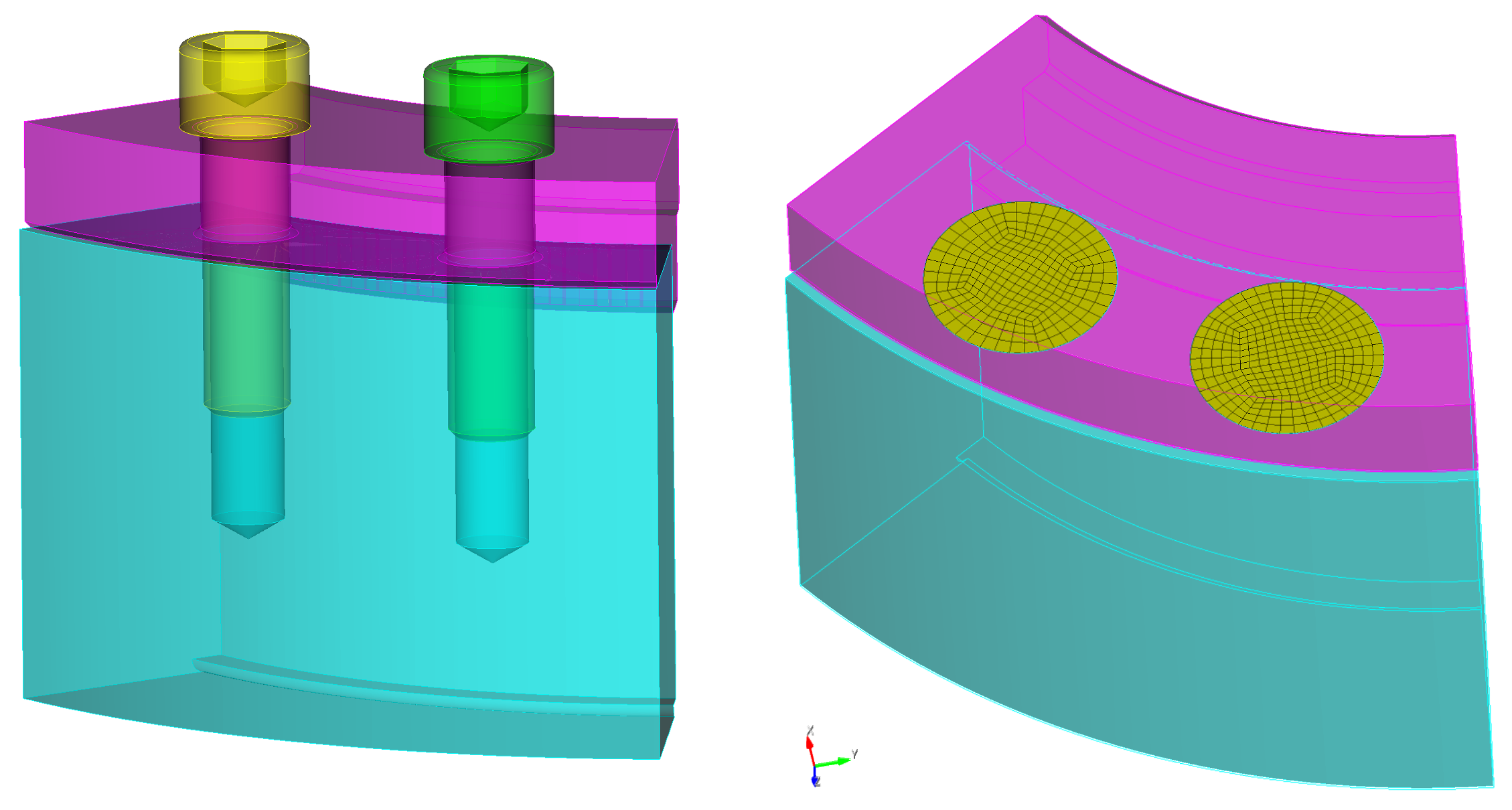
Figure 2. Example of before and after where the reduce bolt patch command has been applied to two bolts. This example uses the mesh and default fill and delete options.
The following outlines the options for the reduce bolt patch command.
You can input either the ID of the bolt to be reduced or the IDs of holes intended for fasteners if no bolt volume is present. Choose between the bolt or hole options based on your specific needs.
bolt
volume <ids>: Specify the ids of the volumes to be reduced. The Geometry Power Tool classification diagnosic can be used for identifying volumes as "bolts".
hole
upper surface <ids> lower surface <ids>: Specify hole IDs for fastener reduction, including at least one surface from both upper and lower holes. Cubit checks axis alignment and matches multiple holes if specified. For more than two fastened volumes, Cubit supports up to three; designate the topmost with >upper surface and the rest with lower surface.
contact upper {surface <ids>} contact lower {surface <ids>}: In rare cases, the reduce patch command may not auto-identify upper and lower contact surfaces. If this occurs, you can manually specify these surfaces to resolve the issue. Note: This option is only available for a single bolt or hole set.
radius {<value>|Factor <ids>|SHIGLEY [angle {<ids>}]}
radius <value>: The Reduce Bolt Patch allows you to directly set the radius by specifying a floating-point value. Use this option to set an absolute value for the sideset radius on the contact surfaces. This value will determine the radius of the resulting imprinted circle where the sideset is defined.
radius factor <value>: The radius factor option allows you to define the radius of the resulting imprinted circle as a multiple of the shank bolt's radius. If no bolt is present and only the hole is specified, the radius will be a multiple of the upper hole's radius.
radius shigley angle <value>: The radius shigley angle option is the default method for determining the radius. It employs a Shigley angle, as outlined in SAND2008-0371 (Figure 1). If no radius specification is provided, the Shigley angle defaults to 30 degrees to compute the radius. This radius is determined by the intersection of the frustum with the surface between the upper and lower volumes.
The circular patch size can vary based on several factors, such as the thickness of the upper volume, the radius of the bolt head, and the length of the bolt. For more comprehensive details, refer to the SANDIA REPORT SAND2008-0371, "Guideline for Bolted Joint Design and Analysis: Version 1.0."
Note: The radius shigley angle option is applicable only when a bolt is specified. If no bolt is present and only the holes are specified, and no radius is given, the radius factor option becomes the default. In such cases, a default factor of 2.5 will be used to compute the radius.
The Reduce Bolt Patch command imprints concentric circular patches onto the surfaces of the upper and lower volumes. If the surfaces on the upper and lower volume do not extend beyond the specified radius, the resulting surfaces will be clipped accordingly.
mesh: Option to specify whether to include meshing as part of the command.
mesh_size <value>: Optionally specify a target mesh size when using the mesh
mesh_scheme <string>: Specify a target meshing scheme. The following meshing schemes can be used for this operation:
FILL|no_fill: The FILL|no_fill option controls hole treatment. By default setting, FILL removes the hole entirely, along with any features like fillets. The no_fill option retains the hole but simplifies it, removing fillets and creating an annulus centered on the hole's axis. The annulus diameter is set by one of the radius options.
DELETE|no_delete: The default behavior of this command is to delete the bolt as part of the operation. However, users have the flexibility to choose whether or not to delete the bolt.no_simplify_hole: The reduce surface patch command, coupled with the no_fill option, is designed to streamline the meshing process by automatically eliminating chamfers, blends, and conical elements from hole geometries. However, the no_simplify_hole switch overrides this behavior, preserving all existing features of the hole's geometry. This can be particularly useful in scenarios where the default simplification process might lead to command failure due to complex hole configurations. Activating this option allows for the continuation of the operation without the standard simplification step.
array_name: This option requires a string value that will be employed as a prefix for all resulting sidesets which are created by the command. When the name_patch_surfaces option is simultaneously activated, this prefix is also applied to the names of any generated surfaces. Therefore, the prefix ensures consistent naming conventions across sidesets and, conditionally, surfaces, streamlining subsequent identification and processing. Note that if the array_name is not explicityly specified, the name prefix "Bolt_Patch" will be prepended to the name of each of the sideset and surface names.Sideset IDs and name assignment: The following options may be used to assign the resulting circular surfaces based on an ID or a sideset name:
Optional increment and start_id arguments are available for both upper and lower sideset ID specifications. When used, these options automatically generate incrementing sideset IDs. For example, if lower_patch_sideset_id is set to 100 and increment_lower_patch_sideset_id is used, new bolt patches will have unique sideset IDs starting from 100 (e.g., 101, 102, 103). If both upper_patch_sideset_id and start_upper_sideset_id (or their lower counterparts) are used with increment, the new patches may be added to the existing sideset and a new, incrementing sideset, effectively adding the same patch to two different sidesets.
name_patch_surfaces: This option allows you to name the surfaces created by the reduce patch command. You can use either default or custom names. Default names are "Upper_Patch" and "Lower_Patch". If you specify names using upper_patch_sideset_name or lower_patch_sideset_name, those names will instead be applied to the resulting circular surfaces. This is helpful for referencing in future scripts or journal commands.Default Naming: Sidesets are automatically named to reflect the connections between components. For instance, for clamped volumes with names "PartA" and "PartB" generates sideset names such as "PartA_to_PartB_123" and "PartB_to_PartA_123." These names encapsulate the parts involved and a unique identifier for the fastener's volume, "_123" in this case. In this example, the name "PartA_to_PartB_123" signifies the sideset on PartA that denotes its interface with PartB, and similarly, "PartB_to_PartA_123" is assigned to PartB to mark its connection with PartA. When blocks are designated and the clamped volumes are assigned, the naming convention defaults to using block names rather than volume names.
array_name + "_" + [NameA] + "_" + [NameB] + "_" + [Volume ID of Bolt]
where NameA designates the name of the volume or block the sideset is attached to and NameB designates the volume or block the sideset is in contact with.
If array_name is set to "Connect", the volume ID of the bolt is 3, and the clamped volume names are "PartA" and "PartB" the resulting sideset names for the resulting sidesets would be:
Connect_PartA_to_PartB_3Connect_PartB_to_PartA_3Alternative Default Naming: Activating the option with sideset_naming_convention set to 1 changes the naming scheme. Sidesets begin with a "Bolt_Patch" prefix (assuming no array_name is given), then add "_Lower" or "_Upper" to indicate their position relative to the bolt's bearing surface, and conclude with a numeric identifier for the bolt volume. This convention offers an alternative to the default, which is applied automatically without needing explicit selection.
array_name + "_" + [Volume ID of Bolt] + "_Upper/Lower"
If array_name is set to "Connect" and the volume ID of the bolt is 3, the resulting sideset names for the upper and lower portions would be:
Connect_3_UpperConnect_3_LowerThis naming applies to surfaces as well when the name_patch_surfaces option is activated. In cases where a single bolt connects more than two volumes, the naming includes the individual connections. For example, a bolt fastening three volumes would yield names such as:
Connect_1_3_UpperConnect_1_3_LowerConnect_2_3_UpperConnect_2_3_LowerHere, the first number represents the index of the connection at the same bolt, and the second number is the volume ID of the bolt.
Be aware that these default naming conventions can be superseded by the explicit naming options, upper_patch_sideset_name and upper_patch_sideset_name, provided in the previous section of this documentation.