Rebar Surface <range> {Diagonal|Orthogonal} [Spacing <int>] [Block <id> [Element Type {bar|bar2|bar3|BEAM|beam2|beam3|truss}]
CUBIT> rebar surf 1 diagonal spacing 2 block 2
CUBIT> rebar surf 1 orthogonal spacing 3 block 3
Cubit 16.04 User Documentation
Element blocks are the method CUBIT uses to group related sets of elements into a single entity. Each element in an element block must have the same basic and specific element type.
The preferred method for defining blocks is to use geometric entities such as volumes, surfaces or curves. Blocks can also be defined using mesh entities. If a block is defined at a geometric entity, each of the elements owned by the geometry are automatically assigned to the block. Deleting or remeshing the geometry automatically changes the set of elements grouped into the block. If mesh entities are used to specify a block, deleting the mesh will also delete the elements from the block.
Some important notes regarding Element Blocks are as follows:
Element blocks are defined with the following Block commands.
Block <block_id> [ADD|Remove] {Vertex | Node} <range>
Block <block_id> [ADD|Remove] {Curve | Edge} <range>
Block <block_id> [ADD|Remove] {Surface | Face | Tri} <range>
Block <block_id> [ADD|Remove] {Volume | Hex | Tet | Pyramid | Wedge} <range>
Block <block_id> [ADD|Remove] Group <range>
These commands define blocks based on a list of geometric or mesh entities. A block can only hold entities of the same dimensionality. For example, a block defined to hold vertices and nodes cannot also hold hexes. The above commands reflect this restriction. This restriction also applies when adding entities using groups. When creating a block using a group containing entities of different dimensionality the behavior is undefined.
Adding geometric entities to a block effectivily adds all mesh entities of the same dimensionality contained in the geometric entity to the block. For example, adding a volume to a block adds all hexes, tets, pyramids and wedges contained in the volume to the block. Removing geometry entities works in the same manner. Thus the following commands:
Block 1 add volume 1
Block 1 remove hex 1
Creates block 1 containing all of the hexes, tets, pyramids and wedges in volume 1 except for hex 1.
When a mesh entity, or a meshed geometric entity is put into a block, it is assigned a Global Element ID which is exported to the exodus file for tracking during analysis.
The following commands can be used to assign a name or description to an element block. Assigning a name to a block can be more intuitive than using traditional integer IDs, and the name and description are preserved in DART metadata-enabled applications (like SIMBA). This command is also available for nodesets and sidesets.
Block<ids> Name "<new_name>"
Block<ids> Description "<description>"
Each block must have a specific element type associated with it. To assign an element type to a block, use the following command:
Block <block_id_range> Element Type <type>
Available element types are defined by the Exodus II file format specification (Schoof, 95). CUBIT supports the following element types:
Nodes: SPHERE SPRING
Curves: BAR BAR2 BAR3 BEAM BEAM2 BEAM3 TRUSS TRUSS2 TRUSS3 SPRING
Surfaces: QUAD QUAD4 QUAD5 QUAD8 QUAD9 SHELL SHELL4 SHELL8 SHELL9 HEXSHELL TRI TRI3 TRI6 TRI7 TRISHELL TRISHELL3 TRISHELL6 TRISHELL7
Volumes: HEX HEX8 HEX9 HEX20 HEX27 TETRA TETRA4 TETRA8 TETRA10 TETRA14 TETRA15 PYRAMID PYRAMID5 PYRAMID13 PYRAMID18 WEDGE WEDGE6 WEDGE15 WEDGE16 WEDGE20 WEDGE21
If the element type is not assigned for an element block, it will be assigned a default type depending on which type of geometry entity is contained in the block. The default values used for element type are:
Volume: 8-node hexahedral elements (HEX8) will be generated for hex meshes. TETRA4 will be generated for tet meshes.
Surface: 4-node shell elements (SHELL4) will be generated for quad meshes and TRISHELL3 for tri meshes.
Curve: 2-node bar elements (BAR2) will be generated.
Node: 1-node elements (SPHERE) will be generated.
set Node Constraint {on|off|SMART [tet quality {distortion|NORMALIZED INRADIUS}][threshold <value=0.15>]]}
On means higher order mid-nodes snap to curved geometry. Off means the mid-nodes retain their positions. “smart” means higher order mid-nodes will only snap to geometry if they do not cause quality problems after being moved. Nodes that cannot be moved without causing quality problems are placed at the average location of the element nodes: for edges, this means on the line containing the edge; for 2d elements, this usually means on the plane containing the element.
When the smart option is used, the tet quality and threshold options can also be used. Tet quality indicates the quality metric that will be used for determining whether mid-nodes will be projected or straightened. This option is currently only valid for high order tets (TETRA10) and tris (TRI6). Normalized Inradius or Distortion metrics may be selected as criteria for projections. The threshold value indicates the quality value at which mid-nodes will not be projected. For example, if Normalized Inradius falls below the threshold value, the element edge will be straightened. Those with metrics above the threshold will be projected.
When exporting an ExodusII file, if the user has not specified any Element Blocks, by default element blocks will be written for any meshed volumes. This default behavior can be changed, to write surface, volume, or no meshes by default. This option can be set using the command
Set Default Block [ON|off|Volume|Surface|Curve]
Default behavior, ON, is for the blocks to automatically be written based on their owning geometry. When the OFF setting is used, only the mesh contained in blocks created by the user will be exported. Mesh not in an element block at export time, will not be exported. The export will still succeed and no error will be thrown. If Volume is specified, only elements contained in volumes will have default blocks specified. Similarly, the Surface or Curve argument indicates that only surfaces or curves containing elements will use default blocks, respectively.
When default blocks are used, the IDs for the resulting blocks will be the ID of the owning geometry.
By default, any given element cannot be included in more than one block. However, when using the following command, an element may be included in more than one block. Please note, since material properties are assigned to blocks, using this command to allow duplicate block elements may result in an element being assigned to multiple materials.
Set Duplicate Block Elements {on|OFF}
Cubit stores only a single Global Element ID (GID) for each element. If an element is placed into more than one block, when the model is exported to Exodus, new additional GIDs will be assigned to the element for each additional block that an element is in. These additional GIDs are exported to the exodus file, but Cubit currently only stores and tracks the first GID assigned.
It may be necessary to associate attributes with a specific element block. Attributes are generally integer or floating point values that represent some physical property in the region occupied by the block, such as material properties or shell thickness. To assign the number of attributes for an element block, use the following command:
Block <id_range> Attribute Count <0-20>
CUBIT will store up to 20 attributes per block. Specify the maximum number of attributes to be stored on the block with this command. Once this command has been executed, individual attributes may be set using the following command:
Block <id_range> Attribute Index <index> <value>
The index is an integer from 1 to the maximum count specified in the Block Attribute Count command. The value may be any valid floating point number.
To assign a value to all attributes of an element block, use the command:
Block <block_id_range> Attribute <value>
Blocks can be viewed individually with CUBIT by employing the following command:
Draw Block <block_id_range> [Color <color_spec>] [add] [thickness [offset [scale <val>] | include_normal]]
For blocks that are of type SHELL and TRISHELL or one of its variants including the [thickness] keyword and parameters will result in the blocks being color-coded by shell thickness with a corresponding color bar. Blocks can be drawn with their specified thickness, so they visually have a thickness. This thickness can also be scaled in the draw command. Arrows defining the shell normal direction will be displayed as well as a legend showing the thickness values.
Block colors can also be changed using the following command:
Color Block <block_id_range> {color|Default}
All Nodesets, Sidesets and Blocks may be deleted from the model using the following command:
Reset Genesis
To remove only Blocks, the following may be used:
Reset Block
To remove a specific block, use:
Delete Block <block_id_range>
The block renumber command gives the user the ability to renumber blocks to fit the user's needs. The command is:
Block <id_range> renumber start_id <id> [uniqueids]
The id_range must include existing entities or the command will fail.
The start_id plus the number of entities must specify a new id space that does not overlap with the existing block ids. In other words, if the current block numbers are 100, 105, 106, and 109, a start_id of 102 would suggest new block numbers of 102, 103, 104, and 105. This would cause an id space conflict and the command will fail.
If the user specifies the uniqueids option, then the new entity id space must not conflict with the existing id space of all blocks, nodesets, and sidesets.
Example:
Assume:
block ids: 100, 105, 106, 109
block all renumber start 20
block 20 renumber start 24
After commands:
block ids: 21, 22, 23, 24
To renumber the elements within a block, see the renumber command
After a mesh has been defined within a volume, it may be useful to use the existing mesh edges as the basis for an element block. Such an element block might be composed of bars or truss type elements that might propagate through a solid medium such as rebar placed in reinforced concrete. Although the Block <id> Edge <range> command could be used for this task, it would prove extremely tedious defining the individual edges to add to the block. To make this process easier, the following command can be used:
Rebar Start <x> <y> <z> Direction <x> <y> <z> [Length <value>] Block <id> [Element Type {bar|bar2|bar3|BEAM|beam2|beam3|truss|truss2|truss3}]
The Rebar command allows the user to specify a starting location for a set of edges and an initial direction. The program will find the closest existing node in the mesh to Start <x> <y> <z> and begin propagating through the mesh in the specified Direction <x> <y> <z>, adding edges to the block as it propagates through the mesh. The edge that is attached to the last node and is within a fixed 30 degrees of the specified direction is added to the block. The Propagation of the edges continues until either the optional Length value is reached or an edge does not meet the Direction criteria. Also required with this command is a block ID. An Element Type can also be specified.
Similarly, you can use the following command which will use the 30 degree cone described above to gather edges from a surface into a single block using the Cartesian x, y, and/or z vectors.
Rebar Surface <range> [x] [y] [z] Block <id> [Element Type {bar|bar2|bar3|BEAM|beam2|beam3|truss|truss2|truss3}] [Propagate]
Another method for generating rebar blocks include the Diagonal/Orthogonal option. This command can only be used on surfaces that have been meshed with the mapping scheme. This command will create a block of edges from the mapped mesh by starting in one corner and gathering edges orthogonally, or creating new edges diagonally based on the option specified, using the parametric coordinate system dictated by the mapping scheme on the surface. The spacing option dictates how many edges are skipped over before starting the next set of rebar edges.
Rebar Surface <range> {Diagonal|Orthogonal} [Spacing <int>] [Block <id> [Element Type {bar|bar2|bar3|BEAM|beam2|beam3|truss}]
CUBIT> rebar surf 1 diagonal spacing 2 block 2
CUBIT> rebar surf 1 orthogonal spacing 3 block 3
A final rebar option allows the user to create or group rebar edges into a specified block using nodes. Edges are created, or gathered, using the ordered list of nodes specified in the command.
Rebar Node <range> [Target Block <id>] [Element Type {bar|bar2|bar3|BEAM|beam2|beam3|truss}]
CUBIT> rebar node 113 105 97 89 81 73 65 57 49 target block 1
A related command for creating curve geometry directly from mesh edges is the Create Curve from Mesh command. See Curve creation for more details.
The block creation tool also allows the user to create a special block of bar elements that can be used as part of the boundary specification. This command creates beam type elements directly without creating any underlying geometry.
The command for creating this type of block is:
Block <id> Joint [Vertex <id> | Node <id> ] Spider {Surface|Curve|Vertex|Face|Tri|Node} <range> [preview] [Element Type {bar|bar2|bar3|BEAM|beam2|beam3|truss|truss2|truss3}]
The joint node is the starting location of the bar elements and the spider location is the terminating location of the bar elements. You can specify the joint node as either a node or a vertex. Optionally, if no joint node is specified, a joint node will automatically be created at the centroid of the nodes on the specified terminating location. You can specify the terminating location as either a node, vertex, geometric surface or the face of a mesh entity.
Some analysis codes refer to these bar elements as tied contacts or rigid bar elements. They can be used to tie models together or to enforce specific kinds of boundary conditions. For example, in the figure below a block of beam elements is used to tie a node at the center of the circle to every node on the edge of the circle. This arrangement can be used to enforce circularity but still allow for displacement of the entire circle. This may occur if there are additional structures above the cylinder that are being excluded from the current finite element model. The beam elements were created by a series of commands of the form
block 10 joint node 1 spider node 2
The preview option can be included to draw the location of the beam blocks on the screen without actually executing the command.
If geometry (surfaces, curves, or vertices) is specified to define the spider, the spider will be 'tied' to that geometry, meaning:
Figure 1. Beam elements created with the Spider command
Properties for blocks that are beam types (beam, beam2, beam3) have additional commands to define a cross-sectional area. The following command can be used to change the type of cross-sectional area of a beam block:
Block <id> beam_type {CIRCLE|box|rectangle|pipe|ibeam|general}
The dimensions are set by listing them after the keyword beam_dimensions:
Block <id> beam_dimensions <values>
The order in which the values need to be specified are described in the chart below.
If the solver used is to integrate over the section during the simulation, turn section_integration on using the following command:
Block <id> section_integration {ON|off}
The beam normal vector is a vector normal to the plane of motion and tangent to the first bending axis. This vector can be set using the following command:
Block <id> beam_normal <x><y><z>
Section Profile |
Order to Specify Dimensions |
| Circle | Radius |
| Pipe | Outer radius, wall thickness |
| Rectangle | Width, height |
| Box | Total width, total height, thickness (right), thickness (top), thickness (left), thickness (bottom) |
| I-Beam | Distance to bending axis (from bottom), total height, bottom width, top width, thickness (bottom), thickness (top), thickness (web) |
| General | Area, Ixx, Ixy, Iyy, Polar moment of inertia (J) |
Spring blocks that will be exported to Abaqus can contain additional properties related to Abaqus springs. Users can specify the spring type, stiffness, and DOFs associated with Abaqus springs. The spring type mapping to Abaqus elements is in the following table.
CUBIT Block Spring Type |
Abaqus Element Type |
| Node_to_node | SPRINGA |
| Node_to_node | SPRING1 |
| Node_to_ground_fixed | SPRING2 |
The spring type is set using the spring_type keyword. In order to use this command, the block must already have an element type of “SPRING.” If a DOF is associated with a spring, the spring_dof_1 keyword is used to specify the DOF on the first node and spring_dof_2 is used to specify the DOF on the second node (SPRING2 only).
Block <id> [spring_type {NODE_TO_NODE | node_to_node_fixed_axis | node_to_ground}] [stiffness <k>] [spring_dof_1 <n>] [spring_dof_2 <n>]
Sphere elements are created in CUBIT by inserting either nodes or vertices into a block.
Block <id> {node|vertex} <id_range>
The command above causes CUBIT to internally create a sphere element and associate it to the inserted node, or to the node associated to the inserted vertex.
Example:
brick x 10
vol all size 5
mesh vol all
create vertex 0 0 10
#{sph_vtx_id=Id("vertex")}
mesh vertex {sph_vtx_id}
#{sph_nd=Id("node")}
block 1 volume 1
block 2 vertex {sph_vtx_id}
block 3 joint node {sph_nd} spider surf 1
locate sphere all
The example commands above will generate the model illustrated in the figure below.
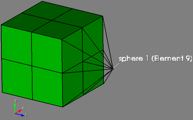
Figure 2. A sphere element created and connected to a solid mesh with 2d elements.
You can interact with sphere elements in Cubit with the commands below:
locate sphere <id_range>
draw sphere <id_range>
highlight sphere <id_range>
list sphere ids
list sphere <id_range>
CUBIT is a 3d mesh generator by default. Element types, by default, are respectively TRISHELL and SHELL for triangle and quad elements. If a 2d mesh is desired, blocks types must be explicitly set to TRI or QUAD.
Example:
create brick x 10
surface 1 scheme trimesh
mesh surface 1
block 1 surface 1
block 1 element type tri
export mesh "mymesh.exo"
Sideset 1 will be based on the TRI and QUAD elements in blocks 1 and 2, with the side numbering referring to the edges of the triangles and quads.
The Set Block Mixed Output command controls the behavior of blocks containing different element types when exporting in a file format that doesn't support blocks with mixed element types. If DEGENERATE, all elements will be exported in one block, but tets and pyramids will be written as degenerate hexes, and triangles will be written as degenerate quads. If OFFSET (set by default), then new element blocks will be created separating the types. Hex and Quad blocks retain the block id, whereas tets, triangle, pyramids and wedges get put into other blocks. The ids of the other blocks are based on the block id plus the offset for that type. Those values are set using the offset commands.
Set Block Mixed Element Output { OFFSET | Degenerate }
Set Block Triangle Offset <value>
Set Block Tetrahedron Offset <value>
Set Block Pyramid Offset <value>
Block <id> Material <id|'name'>
If a material is assigned to an element block, the material properties will be associated with the block's elements when the mesh is exported. If no material is assigned to a block, a default material will be used during export.
Lite import of Exodus files with elements of SUPERELEMENT_TOPOLOGY_XX.
What's currently supported:
What's currently NOT supported: