
Cubit 16.04 User Documentation
Curves are created by specifying the bounding lower-order topology (i.e. the vertices) and the geometry (shape) of the curve (along with any parameters necessary for that geometry). There are several forms of this command:
1. Straight: The first form of the command creates a straight line or a line lying on the specified surface. If a surface is used, the curve will lie on that surface but will not be associated with the surface's topology.
Create Curve [Vertex] <vertex_id> [Vertex] <vertex_id> [On Surface <surface_id>]
Straight curves can be created using an axis. The syntax is as follows:
Create Curve Axis {options}
The length of the axis must be specified. Go to Location, Direction, and Axis Specification to see the axis command description.
Additionally, several connected straight curves can be created with a single command. The syntax for the polyline command is as follows:
Create Curve Polyline Location {options} Location {options} ...
Notice that two or more locations are used to define a polyline. See Location, Direction, and Axis Specification for the location command description.
2. Parabolic, Circular, Ellipse: The parabolic option creates a parabolic arc which goes through the three vertices. The circular and ellipse options create circular and elliptical curves respectively that go through the first and last vertices.
Create Curve [Vertex <vertex_id> [Vertex] <vertex_id> [[Vertex] <vertex_id> [Parabolic|Circular|ELLIPSE [start angle <val=0>] [stop angle <val=90>]]]
If 'ellipse' is specified, Cubit will create an ellipse assuming the vectors between vertices (1 and 3) and (2 and 3) are orthogonal. v1-v3 and v2-v3 define the major and minor axes of the ellipse and v3 defines the center point. These vectors should be at 90 degrees. If not, Cubit will issue a warning indicating the vertices are not sufficient to create an ellipse and will then default to creating a spiral.
The angle options will specify what portion of the ellipse to create. If none are specified, start angle will default to 0 and stop angle to 90 and the ellipse will go from vertex 1 to vertex 2; if the vertices are free vertices they will be consumed in the ellipse creation. Start angle tells Cubit where to start the ellipse -- the angle from the first axis (v1 - v3) specified. Stop angle tells Cubit where to end the ellipse -- the angle from the first axis. The angle follows the right-hand rule about the normal defined by (v1 - v3) X (v2 - v3).
3. Spline: The spline form of the command creates a spline curve that goes through all the input vertices or locations. To create a curve from a list of vertices use the syntax shown below. The delete option will remove all of the intermediate vertices used to create the spline leaving only the end vertices.
Create Curve [Vertex] <vertex_id_list> [Spline] [Delete]
Additionally, spline curves can be created by inputting a list of locations. Where the spline will pass through all of the specified locations. The syntax is shown below:
Create Curve Spline {List of locations}
See Location, Direction, and Axis Specification to view the location specification syntax.
4. Copy: This command actually copies the geometric definition in the specified curve to the newly created curve. The new curve is free floating.
Create Curve From Curve <curve_id>
5. Combine Existing Curves: This command creates a new curve from a connected chain of existing ACIS curves.
Create Curve combine curve <id_list> [delete]
6. Arc Three: The following command creates an arc either through 3 vertices or tangent to 3 curves. The Full qualifier will cause a complete circle to be created.
Create Curve Arc Three {Vertex|Curve} <id_list> [Full]
7. Arc End Vertices and Radius: The following command creates an arc using two vertices, the radius and a normal direction. The Full qualifier will cause a complete circle to be created.
Create Curve Arc Vertex <id_list>
Radius <value> Normal {<x> <y> <z> | {direction options} [Full]
Go to Location, Direction, and Axis Specification to see the direction command description.
8. Arc Center Vertex: The next form of the command creates an arc using the center of the arc and 2 points on the arc. The arc will always have a radius at a distance from the center to the first point, unless the Radius value is given. Again, the Full qualifier will cause a complete circle to be created.
Create Curve Arc Center Vertex <center_id> <end1_id> <end2_id>
[Radius <value>] [Full]
[Normal {<x> <y> <z> | {direction options}]
Go to Location, Direction, and Axis Specification to see the direction command description.
Note: Requires 3 Vertices - first is the center, the other two are the end points of the arc. A normal direction is required when the three points are colinear. Otherwise a normal direction is optional.
9. Arc Center Angle: This form of the command creates an arc using the center position of the arc, the radius, the normal direction and the sweep angle.
Create Curve Arc Center {<x=0> <y=0> <z=0> | {location options}
Radius <value>
Normal {<x> <y> <z> | {direction options}
Start Angle <value=0> Stop Angle <value=360>
Go to Location, Direction, and Axis Specification to see the location and direction command descriptions.
10. From Vertex Onto Curve: The following command will create a curve from a vertex onto a specified position along a curve. If none of the optional parameters are given, the location on the curve is calculated as using the shortest distance from the start vertex to the curve (i.e., the new curve will be normal to the existing curve).
Create Curve From Vertex <vertex_id> Onto Curve <curve_id> [Fraction <f> | Distance <d> | Position <xval><yval><zval> | Close_To Vertex <vertex_id> [[From] Vertex <vertex_id> (optional for 'Fraction' & 'Distance')]] [On Surface <surface_id>]
Note: Default = Normal to the Curve
11. Offset: The next command creates curves offset at a specified distance from a planar chain of curves. The direction vector is only needed if a single straight curve is given. The offset curves are trimmed or extended so that no overlaps or gaps exist between them. If the curves need to be extended the extension type can be Rounded like arcs, Extended tangentially (the default -straight lines are extended as straight lines and arcs are extended as arcs), or extended naturally.
Create Curve Offset Curve <id_list> Distance <val> [Direction <x> <y> <z>] [Rounded|EXTENDED|Natural]
Note: Direction is optional for offsets of individual straight curves only
In all cases, the specified vertices are not used directly but rather their positions are used to create new vertices.
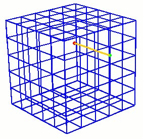
12. From Mesh Edges: This commands creates a curve from an existing mesh given a starting node and an adjacent edge.
Create Curve From Mesh Node <id> Edge <id> [Length <val>]
The adjacent edge indicates which direction to propagate the curve.
The curve will be composed of mesh edges up to the specified length.
If no length is specified the curve will propagate as far as the boundary
of the mesh. Figure 1 shows a example of a curve generated from the mesh.
Figure 1. Example of curve created from mesh
The underlying geometry kernel used for this command is Mesh-Based geometry. The new curve will also be meshed with the edges it was propagated through. A related command for assigning mesh edges directly to a mesh block is the Rebar command. See Element Block Specification for more details.
Note: Full hexes or full tets must be used to propagate the curves through the interior of volume.
13. Close_To This option takes two geometric entities and creates the shortest possible curve between the two entities at the location where the two entities are the closest. The two entities may NOT intersect. If two vertices are given, the command will create a straight line between the two vertices.
Create Curve Close_To {Vertex|Curve|Surface|Volume|Body} <id_1> {Vertex|Curve|Surface|Volume|Body} <id_2>
14. Surface Intersection The following command creates curves at surface intersections. Multiple curves can be created from a single command.
Create Curve Intersecting Surface <id_list>
15. By Projection The project command projects curves, or the curves of a surface another a single surface or multiple surfaces of a volume or body. The command syntax is as follows:
Project { Curve <id_list> | Surface <id_list> } Onto Surface <surface_id> [Imprint [Keepcurve] [Keepbody]] [Trim]
Project { Curve <id_list> | Surface <id_list> } Onto {Body <id> | Volume <id>} [Target_surface <id_list>] [Imprint [Keepcurve] [Keepbody]]
The first form of the command takes a list of curves or surfaces, and a projection surface. If a list of curves is given, the result will be the creation of a set of free curves on top of the projection surface. If a list of surfaces is given, the result will be the same as selecting the curves of the surface (i.e. a group of free curves on the projecting surface).
The second form will imprint the list of curves (or curves of the surface(s)) onto the surfaces of the specified bodies or volumes. The Target_surface option helps when the projection is ambiguous, for example projecting curves onto a thin-walled volume where the projection could be to either side, as shown in Figure 2.
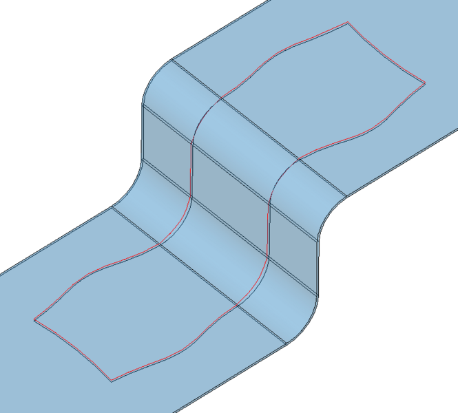
Figure 2. Example of projecting curves to specific side of thin-walled volume.
The imprint option will imprint the resulting projected curves onto the projection surface. If this option is NOT given, the new curves will lie coincident to the surface, but will not be part of the surface. Imprinting changes the topology of the projection surface. Keepcurve option retains the new curves as both free curves, and curves in the projection surface. The keepbody option retains the original body under the new imprinted body. When projecting curves, the trim option will cause the curve to be trimmed to the target surface.
16. Creating a Helix: This command will create a helical curve. The command syntax is as follows:
Create Curve Helix { axis <xpoint ypoint zpoint xvector yvector zvector> | xaxis | yaxis | zaxis } location (options) thread_distance <value> angle <value> [RIGHT_HANDED | left_handed]
axis = axis about which to create the helix
location (options) = starting point of the helix
thread_distance = distance between each 360 degree segment of the helix
angle = number of degrees in rotation of the helix
handedness = right-handed or left- handed threads
17. Tangents: This command will create a spline curve by specifying the end points and the tangents at those points. The command syntax is as follows:
create curve tangent vertex <id> vertex <id> [start direction (options)] [end direction (options)]
create curve tangent start location (options) end location (options) start direction (options) end direction (options)
Both forms of the command can be broken into two parts: the points and the tangent directions. The first point is associated with the start direction.
The first form of the command takes an existing vertex and an optional tangent direction. If the direction is not specified, it will be taken from the tangent at the endpoint of the connected curve. If the vertex is not connected to a curve, or it is connected to multiple curves, the direction must be specified. If the vertex is not connected to a curve, it will be incorporated into the new curve. Otherwise, a new vertex will be created for the new curve.
The second form of the command takes a location and a tangent direction. The directions must be specified and vertices will be created for the locations.
The two command forms can also be mixed. A curve can be created from an existing vertex and a specified location.
Examples:
create curve tangent start location 0 0 0 end location 1 1 0 start direction 1 0 0 end direction 1 0 0
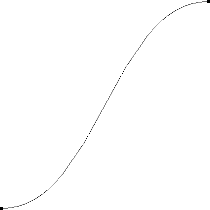
Figure 3. Create tangent curve with locations and tangent directions
create curve tangent vertex 1 vertex 3
merge vertex all
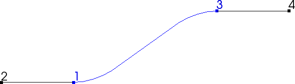
Figure 4. Create tangent curve by specifying vertices on curves. Tangents are extracted from the curve at the vertex location.
Go to Location, Direction, and Axis Specification to see the location and direction command description.