Meshing Tools
The meshing power tool provides a tool for determining whether a geometry
can be meshed using autoscheme,
or if it requires its scheme to be set explicitly. This tool is designed
to help guide users through geometry decomposition process by providing
a convenient way to see which geometries need further modification or
decomposition prior to meshing.
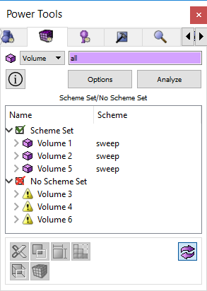
Figure 1. Meshing Power
Tools
Entity Specification- The
meshing power tool works for volumes or surfaces.
Options Button - Opens the
Tools>Options dialog to change the visualization colors
of surface schemes for the meshing tool
Analyze Button - The Analyze
button issues the autoscheme command for all selected volumes and surfaces.
Output Tree - The output
from the meshing tool is displayed in tree format. Geometry is divided
into "Scheme Set" and "Scheme Not Set" divisions.
The geometry is listed under these nodes. If autoscheme was successful,
its assigned scheme is also displayed.
Toggle Visibility Button
- The meshing tool displays entities as red or green in the graphics window.
Green means that they are currently meshable using the autoscheme. Red
means that they require their scheme to be set explicitly. Turning this
capability off will return the volumes and surfaces to their original
colors.
Meshing Tools Buttons -
Several meshing tools are available to the user from this window. Depending
on the entity selected, these are also available from the right-click
context menu, and they are described below.
Right Click Context Menu
- Zoom To - Zoom
in on this element in the graphics window
- Draw - Draw
this entity by itself in the graphics window
- Locate - Locates
and labels entity in the graphics window
- Rotate About - Issues
Rotate
about command for selected entity
- Visibility On/Off -
Toggle visibility
- Reset Graphics- Reset
graphics display
- Set Size - Opens the
Mesh/Entity/Interval panel on the control panel where you can set
interval
sizes for the selected geometry
- Set Scheme - Opens
the Mesh/Entity/Mesh panel on the control panel where you can set
a scheme
for the selected entities
- Set Vertex Type - Available
when surfaces are selected. Opens the Mesh/Surface/Mesh panel to set
vertex types.
- Imprint/Merge- Opens
the Geometry/Entity/Merge panel on the control panel. If you have
entities selected in the tree window it will input them to the imprint/merge
command.
- Webcut - Opens the
Geometry/Volume/Webcut panel on the control panel. If a volume is
selected in the meshing tool window it will input it in the webcut
panel.
- Color Surfaces - Color
surfaces based on their schemes. You can change the default colors
by selecting the Options
button.
- Restore Colors - Restores
colors on selected entity or entity type
- Mesh - Meshes
the selected entities (bypassing control panel)
- Delete Mesh - Deletes
the mesh on selected entities
- Unmerge - Unmerges
selected entities
- View Descendants -
Opens a list of child entities and their meshing schemes. Press Analyze
to return.
- View Ancestors- Opens
a list of parent entities and their meshing schemes. Press Analyze
to return.
- View Neighbors- Opens
a list of bordering entities and their meshing schemes. Press Analyze
to return.