- Product Description
- Product Highlights
- Contact Information
- New Features
- Limitations
- Defects Fixed
- Enhancements
- Documentation
- Contents of Release
- Platforms Supported
Product Description
CUBIT™ is a full-featured software toolkit for robust generation of two- and three-dimensional finite element meshes (grids) and geometry preparation. Its main goal is to reduce the time to generate meshes, particularly large hex meshes of complicated, interlocking assemblies.
Product Highlights
Meshing: CUBIT™ is a solid-modeler based preprocessor that meshes volumes and surfaces for finite element analysis. Mesh generation algorithms include quadrilateral and triangular paving, 2D and 3D mapping, hex sweeping and multi-sweeping, tet meshing, and various special purpose primitives. CUBIT™ contains many algorithms for controlling and automating much of the meshing process, such as automatic scheme selection, interval matching, sweep grouping and sweep verification, and also includes state-of-the-art smoothing algorithms.
Geometry Preparation: One of CUBIT™’s strengths is its ability to import and mesh geometry from a variety of CAD packages. CUBIT™ currently integrates the ACIS and Catia geometry kernels directly within its code base, allowing direct manipulation of the native CAD geometry format within CUBIT™. This reduces the errors and anomalies so often associated with geometry translation. CGM (Common Geometry Module) also boasts a facet-based geometry kernel developed at Sandia that can be used for remeshing or editing old mesh files or models defined by triangle facets. In addition, CUBIT™ has developed a comprehensive virtual geometry capability that permits local composites and partitions to geometry without modifying the underlying native geometry representation. The user can choose to ignore, clean-up or add features to the model allowing greater flexibility to meshing algorithms to generate better quality elements.
CUBIT™ Environment: CUBIT™ has developed both a convenient command line interface with an extensive command language as well as a polished graphical user interface environment. The GUI is based upon the cross-platform standard Qt, which allows the same look and feel on all supported platforms. Also included is a graphical environment based upon the VTK graphics standard which has been optimized for display and manipulation of finite element data and geometry. Fast, interactive manipulation of the model is a tremendous advantage for models with thousands of parts or millions of elements.
For more information on CUBIT™, including licensing arrangements and terms see the CUBIT™ website https://cubit.sandia.gov
New Features in CUBIT™ 15.7
Index of New Features
- New Geometry Power Tool Diagnostics and Solutions
- Machine Learning Tools for Defeaturing and Part Classification
- Display Volume Overlaps and Neighbors from Context Menu
- Tetmesh and Trimesh GUI Command Panels
- Reduce Bolts Command Panel
- New Meshing collapse commands
- Enhancement to meshedit command
- Mesh intersection group naming
- Normalized Inradius metric for tet10 elements
- New Node Constraint Options
- Enhancements to Free Entity Selection
- No more highlight color collisions
- Case insensitive names
- UMR Lite Now Supports Refinement to Geometry
- New CubitInterface Functions
- New Gitlab repository of user-developed Python scripts
Graphical User Interface
New Geometry Power Tool Diagnostics and Solutions
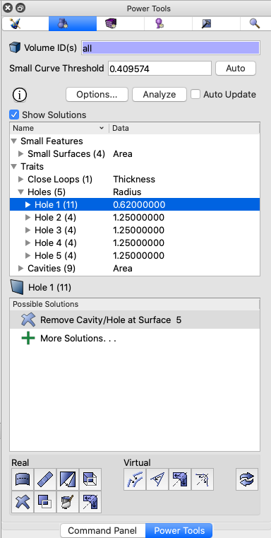
The Geometry power tool includes interactive diagnostics and solutions for defeaturing and repairing CAD models. New diagnostic tests have been added along with rapid solutions for repair. Updated and expanded diagnostics categories include Traits and Assembly Checks
- Traits – This category includes tests for common surface configurations in a geometric volume. This release introduces new and improved Traits diagnostic tests:
- New Holes and Chamfer Chains diagnostics tests allow for rapid identification of these common characteristics so users can quickly remove or verify them. These tests identify sorted lists of collections of surfaces that can be expanded and visualized. Collections of Holes and Chamfer chains are sorted by radius and thickness respectively. New associated context solutions also provide for fast removal of selected collections of surfaces.
- The Blend Chains diagnostic test replaces the Blends diagnostic. Blend Chains now identifies sorted collections of blends that are associated with the same blend chain. This allows rapid identification and removal with a single command.
- Assembly Checks – The new Assembly Checks category of diagnostic replaces Overlap Checks. It consolidates all diagnostics for checking interactions between volumes in an assembly into one category and adds additional valuable tools for resolving issues prior to imprinting, merging and meshing.
- The new Volume Gaps test will display pairs of volumes that are not touching but are closer than the Volume Gap threshold.
- Volume Overlaps is now updated to generate contextual simplified solutions for removing overlaps between pairs of volumes.
- The new Volume Misalignments diagnostic test will identify volumes that are touching but have entities that would otherwise create slivers when imprinting. This also includes new capabilities for quickly visualizing and resolving misalignments between volumes.
- Volume Contacts replaces the Overlapping Surfaces diagnostic. It identifies volume pairs that are touching, but have not been merged along with their overlapping surfaces.
- The new Mergeable Geometry diagnostic replaces the individual vertex, curve and surface mergeable categories. This diagnostic includes entities that are coincident and can be merged.
- A new option for specifying Tolerant Imprint and estimating an Imprint Tolerance is now provided. Changing the Imprint Tolerance can change the results of the Gap, Overlap and Misalignment diagnostic results.
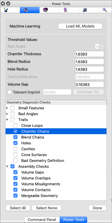
Machine Learning Tools for Defeaturing and Part Classification
This new capability enhances the Geometry Power Tool using state-of-the-art machine learning methods to predict meshing outcomes, suggest solutions as well as classify certain common part types. To activate the machine learning capabilities, click the Load ML Models button in the Options panel of the Geometry Power Tool.
Once Machine Learning has been activated, two new diagnostics in the Geometry Power Tool will appear:
- Tet Mesh Quality Prediction – This diagnostic will provide a list of entities (vertices, curves, surfaces) that are predicted to result in poor quality tet elements sorted by their predicted mesh quality metric. Context solutions for defeaturing are also provided based on prediction from new machine learning models.
- Part Classification – This new diagnostic classifies volumes according to several common part types including:
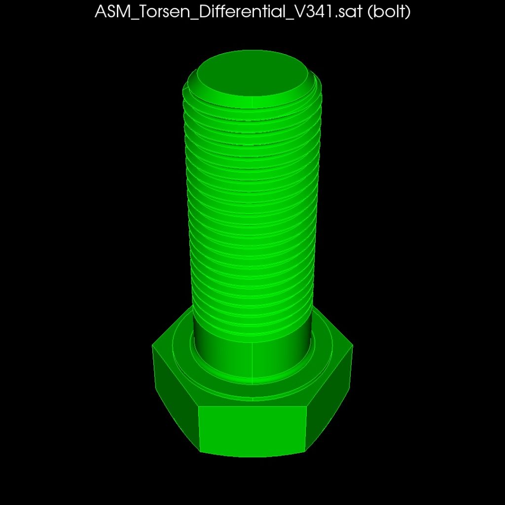
Bolts 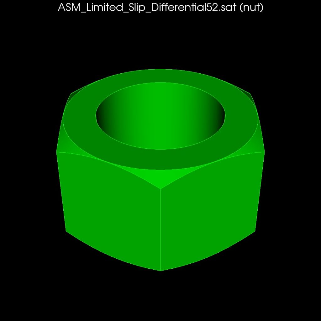
Nuts 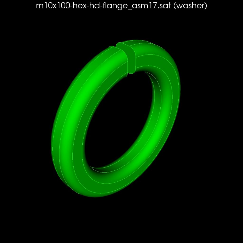
Washers 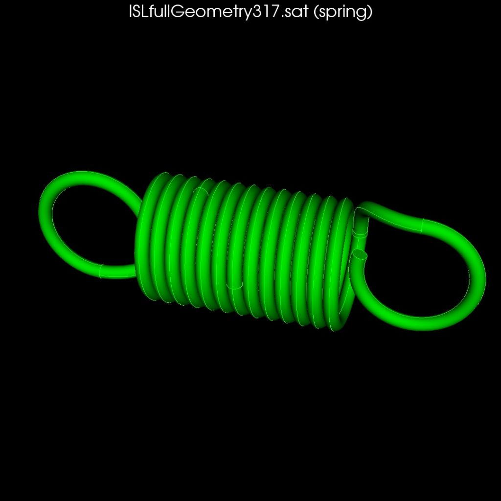
Springs 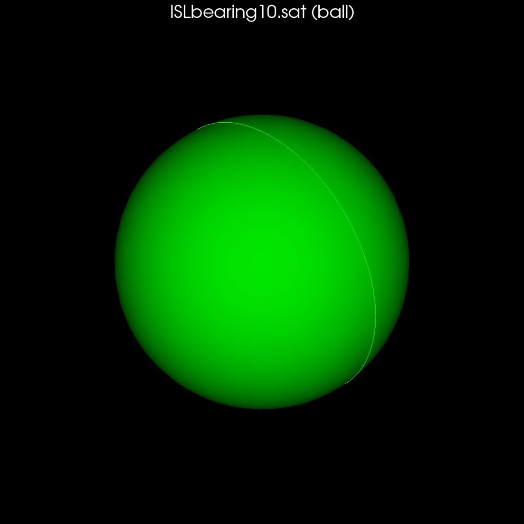
Balls 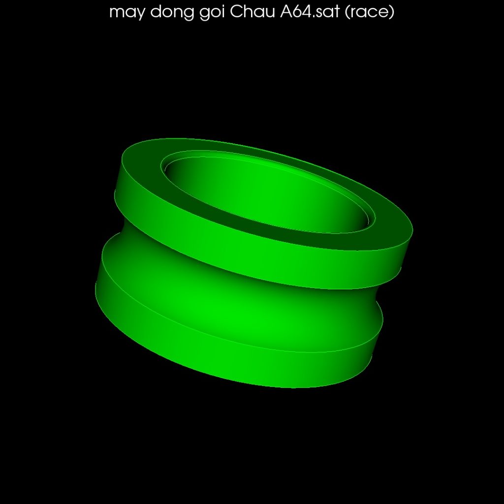
Races 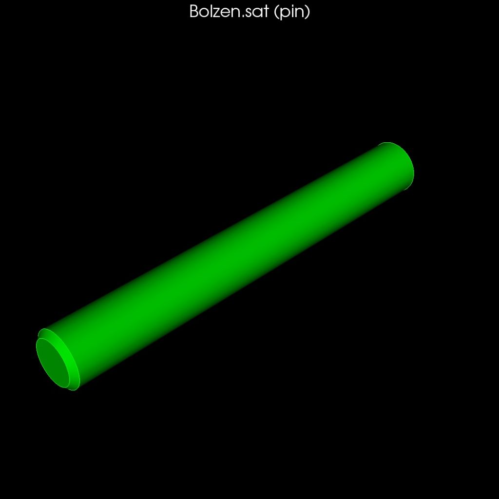
Pins 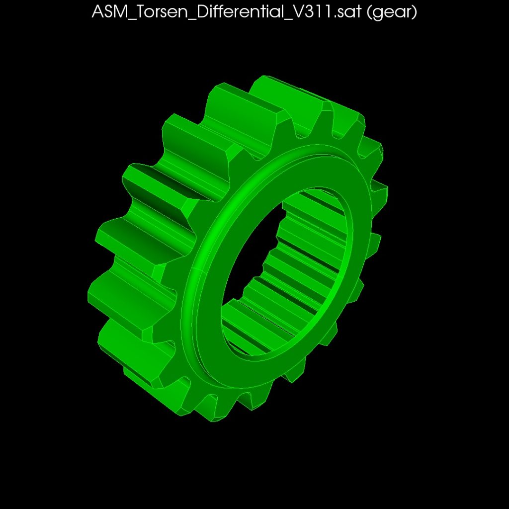
Gears 
Other Parts
Display Volume Overlaps and Neighbors from Context Menu
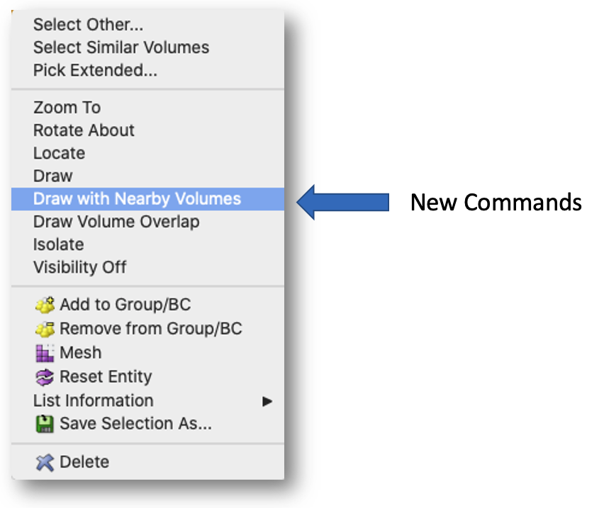
Two new options are available in the graphics window when volumes are selected:
- Draw Nearby Volumes – All volumes close to the selected volume(s) will also be drawn. This is useful when working with large assemblies to view only local parts for defeaturing or boundary condition assignment.
- Draw Volume Overlaps – Draws the wireframe representation of the selected volume(s) and any volumes it overlaps. The overlapping region shared by the volumes will be displayed in red.
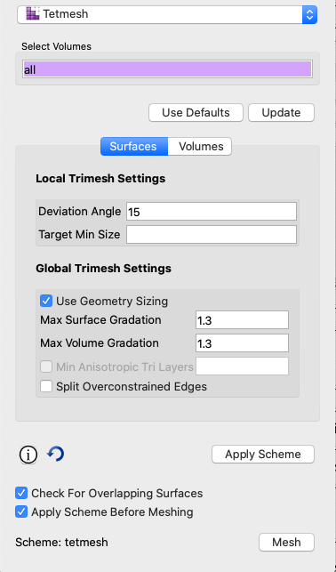
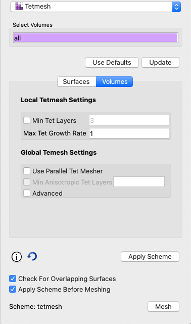
Tetmesh and Trimesh GUI Command Panels
A new command panel for setting options for the tetmesh scheme is now available supporting all new local and global options for tet meshing. This panel now includes two separate tabs for setting options for surface meshing and volume mesh options. The trimesh panel has also been updated in a similar manner for setting options for the trimesh scheme.
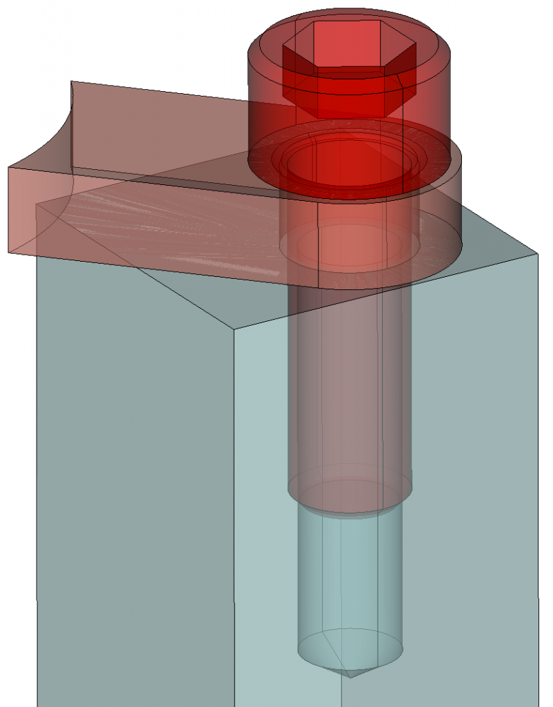
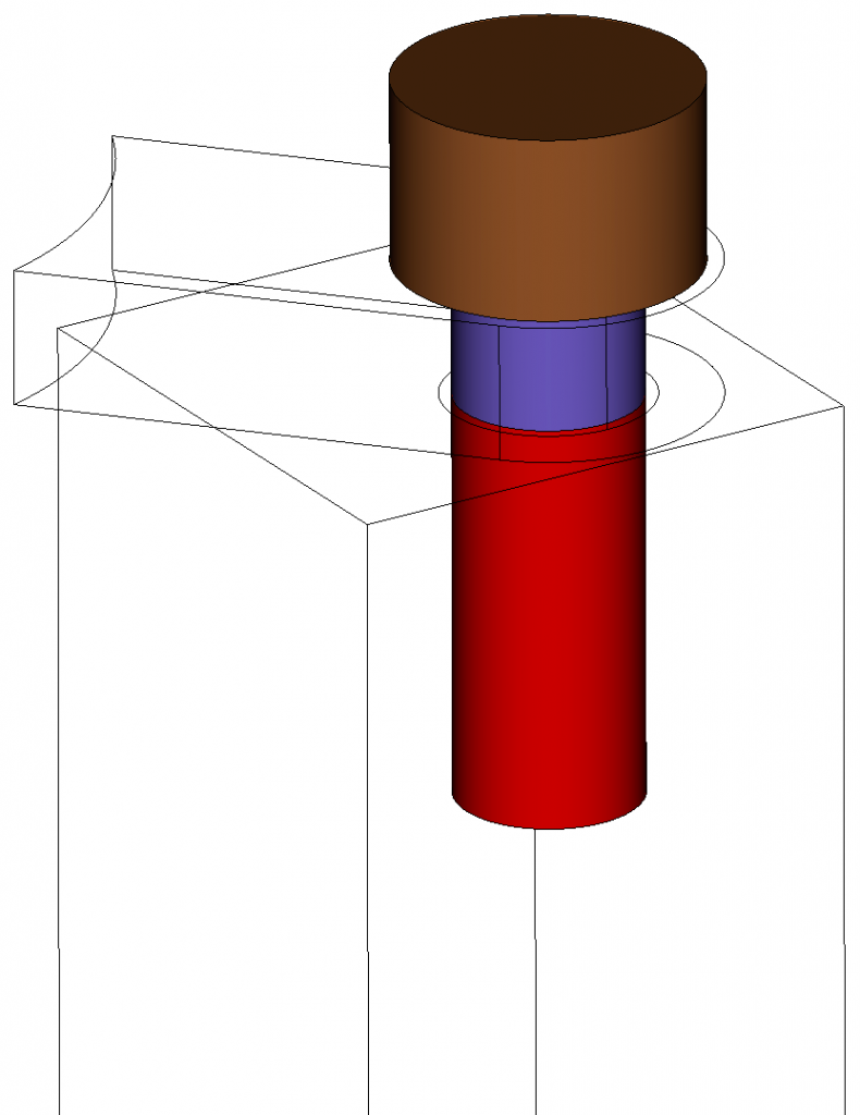
Reduce Bolts Command Panel
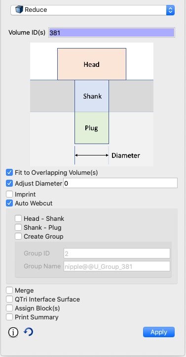
The new Reduce command (described below) uses a new command panel to rapidly set up parameters to simplify and assign boundary conditions to bolt connectors. It can also be invoked from the new Machine Learning tools when bolts have been classified allowing easy selection and processing of multiple bolts in the same command. Access the Reduce options in the command panels by clicking on Mode:Geometry; Entity:Volume; Action:Modify and using the dropdown to select Reduce.
Meshing
New Meshing collapse commands
The following commands are meant to collapse low quality tets and triangles. The user specifies mesh entities to collapse and optionally a metric. The operation attempts to collapse the specified entities, ensuring that the quality of surviving neighbor mesh entities does not degrade lower than the mesh entities getting collapsed. The specified metric is used to determine quality. If not specified, “Scaled Jacobian” is used. If the collapse cannot be done without degrading quality, no collapse is performed. To collapse triangles, use the first two commands. Only triangles and tets can be collapsed, not faces and hexes.
Collapse Edge <ids> [SCALED JACOBIAN|Aspect Ratio|Shape|Shape and Size]
Collapse Tri <ids> [SCALED JACOBIAN|Aspect Ratio|Shape|Shape and Size]
Collapse Tet <ids> [Altitude|Aspect Ratio|Aspect Ratio Gam|Distortion|Inradius|Jacobian|Normalized Inradius|Node Distance|SCALED JACOBIAN|Shape|Shape and Size|Timestep]
Enhancement to meshedit command
The [keep node<id>] option prescribes which node to collapse the edge to. The [compress_ids] option was also added to preserve the previous behavior of compressing the mesh id space after the collapse.
Meshedit Collapse Edge <id> [keep node <id>] [compress_ids]
Mesh intersection group naming
A new option was added to the Find Mesh Intersection command to allow naming the group created containing the intersecting mesh. If not group name is specified, the group is named ‘mesh_intersect’ for 3D elements and ‘surf_intersect’ for 2D elements.
Find Mesh Intersection {Block|Body|Surface|Volume} <id_list> [with {Block|Body|Surface|Volume} <id_list>] [low <value=0.0001>] [high <value=0.0001>] [exhaustive] [worst <num_worst>] [draw] [log] [group <'name'>]
Normalized Inradius metric for tet10 elements
A new quality metric Normalized Inradius is now included as a standard option for all quality commands that effect tets and tris. It is intended to measure quality of TETRA10 and TRI6 elements, but can also measure linear (TETRA4, TRI3) elements. While most tet metrics, such as the default Shape, only take into account the 4 corner nodes of the tet, the Normalized Inradius uses the ten nodes of the tet. This is especially useful when measuring quality for a coarse tet mesh at curved surfaces where mid-edge-nodes can be projected to geometry distorting the elements. An example of using the new metric in a command to display the mesh quality is as follows:
Quality Volume All Normalized Inradius Draw Mesh
New Node Constraint Options
When tet meshing with TETRA10 elements or setting a block element type to TETRA10, the mid-edge nodes on the surfaces can be projected to follow the geometry. In some cases, those projections can form an invalid or poor quality element when the linear version of the elements would otherwise be acceptable. Previously, CUBIT™ provides the set node constraint command to control mid-edge node projections. The SMART option allows for projections only if element quality does not degrade below a quality threshold. This version provides a new tet quality parameter and threshold parameter.
Set Node Constraint [on|off|SMART][tet quality [distortion|NORMALIZED INRADIUS]] [threshold <value=0.15>]
With the introduction of the Normalized Inradius metric this release, the tet quality setting can use this new metric as criteria for projecting mid-edge nodes. The new threshold value permits setting of a value at which mid-edge nodes will be straightened if the quality falls below. The node constraint options can also be set in the Options or Preferences dialog under Mesh Defaults and can be saved between CUBIT™ runs.
Geometry
New Reduce Command
The reduce command prepares a bolt for analysis by quickly breaking down its geometry into its simplest form and applying boundary conditions. The different options allow the bolt to be simplified, decomposed into its component parts, overlap removed and fitted to surrounding geometry, imprinted and merged with surrounding geometry, meshed with a qtri scheme on the plug volume, and more. When used with Cubit’s new Machine Learning capabilities and Reduce GUI Panel, this new tool facilitates significant reduction in time to analysis for models with many bolts. The full command syntax for the command is:
Reduce {volume<ids>} [fit_volume] [webcut [{Head|Shank|BOTH}]]
[imprint] [merge][qtri] [increment_block_ids] [summary] [diameter <value>]
[group_id{<value>|Default}] [group_name {<string>|Default}]
[head_block_id{<value>|Default}] [head_block_name {<string>|Default}]
[shank_block_id{<value>|Default}][shank_block_name {<value>|Default}]
[plug_block_id{<value>|Default}] [plug_block_name {<string>|Default}]
[bolt_block_id{<value>|Default}] [bolt_block_name {<string>|Default}]
Groups persist across webcut
When a volume or body of a group is split in a webcut operation, the resultant pieces of the webcut will also be in the group.
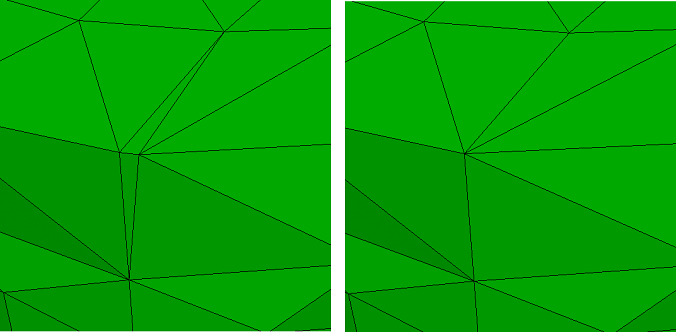
Sculpt
HTET unstructured option
Sculpt now provides an option for splitting hexes into tets using an unstructured method where each hex is subdivided into six tets. Previously only the structured approach was available which split each hex into 24 tets. The new unstructured approach, shown below will not additional nodes to the mesh.
Right: Unstructured htet_method subdivides each hex into 6 tets
Thicken void
A new option for ensuring physical separation between elements of different material blocks is now provided. The new thicken_void option will insert elements designated as the void block material where non-void blocks would otherwise be in contact.
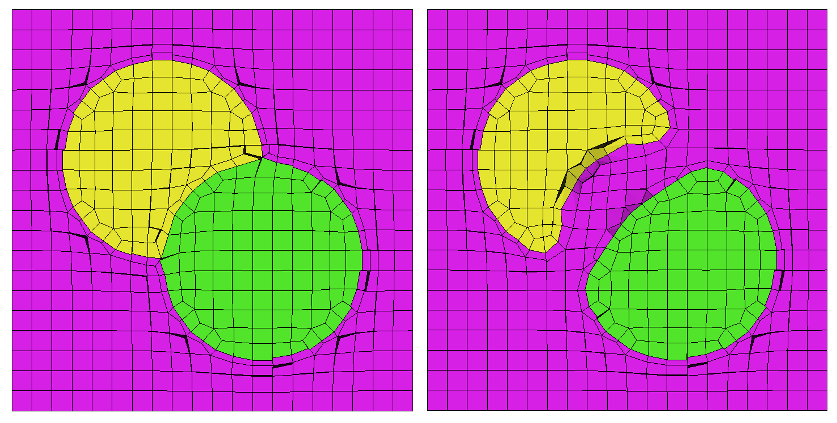
Right: Mesh with thicken_void=1. Void material (Magenta elements) is
inserted between the yellow and green materials to ensure separation.
Better fitting to STL
Using the capture=5 option in Sculpt, mesh is fitted to the input STL. Sculpt now associates the grid edges of the reference mesh to the STL curve geometry. This is an extra level of association, in addition to the grid faces associated to the STL surface geometry. The result is better conforming of the mesh to the STL.
Color smoothing improvement
Color smoothing (spot optimization) in sculpt now extends smoothing out one additional layer of nodes after the first smoothing iteration, ensuring better quality.
Graphics, Utilities, etc.
Enhancements to Free Entity Selection
The ability to select free surfaces (sheet bodies) has been added to the command:
Select Free [surface <id_list>] [curve <id_list>] [vertex <id_list>] [add|remove]
No more highlight color collisions
The automatic colors that CUBIT™ assigns to entities have been slightly changed to avoid colors that are too close to the highlight color, which previously made it difficult to see what was highlighted.
Case insensitive names
When naming entities in CUBIT™, names are now case insensitive. If a model contains volumes with same name, the volume names will be automatically modified during import. Please refer to the user manual if you want the old behaviour.
UMR Lite Now Supports Refinement to Geometry
The Uniform Mesh Refinement (UMR) tool refines a mesh stored in the Exodus format, uniformly splitting every element in the mesh into a number of sub-elements, and writes the fine mesh to a new Exodus file. The resulting elements have roughly half the edge length of the original mesh. The algorithm uses an efficient streaming pipeline with low memory requirements. On recent CPUs with an SSD (solid state drive), it will write a mesh up to 4 billion elements or nodes in only a few minutes, and millions of elements or nodes in seconds or less.
In this beta release of UMR, only blocks and sidesets of tetrahedra (4 node) and triangles (3 node) are supported. When a geometry file (STEP format) is provided, projection of new nodes to geometry or smoothing is performed. Each TET element results in 8 new TET elements, each TRI results in 4 new TRI elements. Resulting blocks and sidesets in the output mesh will have the same IDs and names as the input mesh.
New CubitInterface Functions
CubitInterface is CUBIT™’s python module that provides extensive capability for querying and modifying data in CUBIT™. The following functions were added to CubitInterface for version 15.6.
| Function Name | Description |
| get_total_bounding_box | Get the bounding box for a list of entities. |
| gather_surfaces_by_orientation | Gathers connected surfaces to those specified, that use shared curves in an opposite sense. |
| get_overlapping_surfaces_in_bodies | Returns a list of lists of overlapping surfaces. First surface in each list overlaps with all others in that list. |
| get_chamfer_surfaces | Get the list of chamfer surfaces for a list of volumes |
| get_chamfer_chains | Returns the chamfer chains for a surface |
| get_blend_chain_collections | Returns the collections of surfaces that comprise blend chains in the specified volumes. Filter by radius threshold |
| get_chamfer_chain_collections | Returns the collections of surfaces that comprise chamfers in the specified volumes. Filter by thickness of chamfer |
| get_overlapping_curves | For every occurance of two overlapping curves, two curve ids are returned. |
| get_overlapping_surfaces_at_surface | Get the list of overlapping surfaces for a single surface |
| get_volume_gaps | For every occurance of a gap between volumes, two surfaces ids are returned. |
| get_coincident_entity_pairs | Get the list of coincident vertex-vertex, vertex-curve, and vertex-surface pairs and distances from a list of volumes |
| get_nearby_volumes_at_volume | Get the list of nearby volumes for a single volume within a specified distance |
| get_blunt_tangency_default_depth | get default depth value for blunt tangency operation |
| is_chamfer_surface | Return whether a given surface is a chamfer |
| measure_between_entities | Returns the distance between two specified entities |
| get_tetmesh_growth_factor get_tetmesh_parallel get_tetmesh_num_anisotropic_layers get_tetmesh_optimization_level get_tetmesh_insert_mid_nodes get_tetmesh_optimize_mid_nodes get_tetmesh_optimize_overconstrained_tets get_tetmesh_optimize_overconstrained_edges get_tetmesh_minimize_slivers get_tetmesh_minimize_interior_points get_tetmesh_relax_surface_constraints | Retrieve the current tetmesh global settings (Meshgems) |
| get_trimesh_target_min_size get_trimesh_geometry_sizing get_trimesh_num_anisotropic_layers get_trimesh_split_overconstrained_edges get_trimesh_tiny_edge_length get_trimesh_ridge_angle | Retrieve the current trimesh global settings (Meshgems) |
New Gitlab repository of user-developed Python scripts
A repository has been established to allow users to share python scripts they have developed with the community. These scripts are tested nightly against multiple versions of CUBIT™ on all three platforms.
Defects Fixed in CUBIT™ 15.7
The following items are the user-reported bugs fixed since the last release of CUBIT™. For more information contact Roshan Quadros (wrquadr@sandia.gov).
| Ref # | Description |
| 2859 | Draw curve all produces error on composited surface |
| 3103 | Extended selection *.py files not showing up on Mac |
| 3485 | Spurrious warning on cub import |
| 3710 | CUBIT™ slow to select with a long command string |
| 3791 | Draw command outputs commands when nothing to draw |
| 4045 | Dark mode on mac – model tree font matches the background color |
| 4065 | Model tree needs refresh event after import |
| 4116 | Crash – on merge all |
| 4117 | Draw vol not is_meshed” produces ERROR if everything is meshed |
| 4158 | Nastran Export Issue |
| 4310 | Selecting free vertex, curves and surfaces with is_free |
| 4440 | Crash in RelWithDebInfo mode on Windows |
| 4504 | SAW client has flashing graphics on Windows |
| 4519 | Case sensitivity not respected in new parser help strings |
| 4609 | MGT Function |
| 4615 | Unique_genesis_ids not working with import ‘filename.cub’ |
| 4632 | Change to fire ray output |
| 4646 | Have an explicit option to name a new group |
| 4648 | Bug with list geometry after volume regularization |
| 4691 | Old attributes remain when importing cub file |
| 4694 | Update get_total_bound_box documentation |
| 4695 | Node moving (smoothing) bug in CUBIT™ 15.6 |
| 4697 | Bug with selecting entities in CUBIT™ 15.6 |
| 4701 | Group_names_ids() missing from documentation |
| 4703 | Crash – get_sub_elements |
| 4737 | Nastran exporter broken since 15.4 |
| 4740 | Segfault in CUBIT™ python module when importing an exodus database |
| 4743 | Extraneous Command Output for volume copying |
| 4747 | Add query for material types for all blocks in a CUBIT™ session |
| 4755 | Update netcdf |
| 4768 | Selection not recognised in batch mode |
| 4772 | Python 3.7 with CUBIT™-alpha – error loading shared object |
| 4774 | Draw command outputs commands when nothing to draw |
| 4786 | Equivolume and equiangle unrecognized |
| 4787 | Documentation update – Mesh Refinement |
| 4835 | Bug in splitting surface using “close_to” |
| 4864 | Typo when trying to export quality metric from a lite mesh |
| 4866 | Crash – tetmeshing with MeshGems 2.11 |
| 4959 | Performance issue with recent merge of parser changes |
| 4974 | Misplacement of higher-order mid-face nodes during smoothing |
| Avoid generation of a new volume in surface removal on multiple shell volume | |
| ‘Simplify’ command respects vertices now. Not respected previously | |
| Hardlines can now be parsed with ‘num_parents=1’ |
*The defects listed above are only those user-reported issues deemed “critical” or “blocker”. For information on other known defects contact Roshan Quadros.
Enhancements in CUBIT™ 15.7
The following items are the user-enhancements implemented in the release of release of CUBIT™. For more information contact Roshan Quadros (wrquadr@sandia.gov).
| Ref # | Description |
| 205 | Can’t have return carriages within for loops in a CUBIT™ python script |
| 380 | Keep volume in group after a webcut and reflections |
| 618 | Exodus-based surface mesh sizing by function |
| 660 | Select surface based on angle |
| 3528 | Sierra mesh_scale to use more updated version of CUBIT™ |
| 3535 | Update CUBIT™ component snap shot in Sierra repository |
| 4627 | Create standalone Sculpt CMake for Alegra |
| STL import performance improvement | |
| Import Mesh-based geometry performance improvement on models with large sidesets | |
| Enhanced meshing of composites. Better underlying faceting from ACIS | |
| Improved robustness in blunt tangency command | |
| ‘Topology check coincident node’ works off absolute distance instead of distance between bounding boxes | |
| Fix for inability to create group in quality command using ‘node distance’ metric | |
| Allowing blocks to persist through unite operation with ‘include_mesh’ option |
Limitations in CUBIT™ 15.7
The following items are limitations in the current release of CUBIT™.
| Ref # | Description |
| 3433 | Superelement export not supported |
| CUBIT™ doesn’t work on cee-compute003 and cee-compute004 due to graphics card incompatibility | |
| CUBIT™ is not supported on RHEL6 machines |
Documentation Updates
The CUBIT™ 15.7 online documentation may be found here. A PDF version is also available for download. The CUBIT™ GUI installation also includes the full user documentation included with the program. The user’s manual may be accessed from the Help menu.
CUBIT™ 15.7 Contents of Release
CUBIT™ Program: The installation package includes executables and libraries, packaged in tar.gz files for Linux machines. For Windows, the package is in a self-installing executable, and for Mac OS X a .dmg file is provided. Both a command line and GUI version of CUBIT™ are included with the installation package for all platforms.
Documentation: Linux, Windows and Mac versions include full online documentation. Windows also includes .chm (Windows Help File), of the complete documentation that can be run separately from CUBIT™.
Platforms Supported
CUBIT™ 15.7 supports the following Platforms:
- Linux RedHat Enterprise 7 and 8
- Windows 10, 8 and 7
- macOS 10.11+
Non-Sandia Users
CUBIT™ is freely available for United States government use. For more information on licensing CUBIT™, including academic, commercial, and all other use, go to our licensing page. For current CUBIT™ users, CUBIT™ 15.7 may be downloaded from the CUBIT™ download page.
Sandia Personnel Only
CUBIT™ 15.7 may be downloaded from the CUBIT™ download page.
Windows
Download a Windows installation file and double-click to install.
MAC OS X
Download a Mac OS X disk image file. After the disk image is opened, click and drag the CUBIT™ folder to /Applications.
LINUX LANS
Check with your local LAN administrator for instructions on how to access CUBIT™ on your local LAN. In most cases typing one of the following commands at the UNIX prompt should allow you to execute CUBIT™. In some cases, the full path will need to be specified:
/projects/cubit/<cubit_command>
| cubit | The latest released version (15.7) of CUBIT™ deployed to the LAN. |
| cubit -nogui | The latest released version (15.7) with just the Command Line and graphics window |
| cubit -nogui -nographics | The latest released version (15.7) with just the Command Line |
| cubit-15.7 | Version 15.7 with GUI |
| cubit-beta | The latest beta version still in development |
Contact Information
CUBIT™ Help
For general technical questions including download, installation and CUBIT™ technical assistance.
CUBIT™ Licensing and Passwords
Email: cubit-req@sandia.gov
CUBIT™ Support Lead
Trevor Hensley
Phone: 505-284-7756
Email: cubit-help@sandia.gov
CUBIT™ Project Lead
Roshan Quadros
Sandia National Laboratories
Computational Simulation Infrastructure (org. 1543)
Phone: 505-844-0408
Email: wrquadr@sandia.gov
Sandia National Laboratories is a multi-mission laboratory managed and operated by National Technology & Engineering Solutions of Sandia, LLC., a wholly owned subsidiary of Honeywell International, Inc., for the U.S. Department of Energy’s National Nuclear Security Administration under contract DE-NA0003525. SAND2017-6996 W