Cubit 16.04 User Documentation
Import [Facets|AVS] ''<filename>" [Feature_Angle <angle>] [LINEAR||Spline] [MERGE|No_merge] [Make_elements] [Stitch] [Improve]
Import STL ''<filename>" [Feature_Angle <angle>] [Surface_Feature_Angle <angle>] [LINEAR|Gradient|Quadratic|Spline] [MERGE|No_merge] [Make_elements] [Stitch]
Import OBJ ''<filename>" [Feature_Angle <angle>] [Surface_Feature_Angle <angle>] [Make_elements]
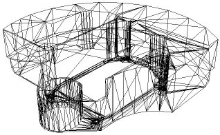
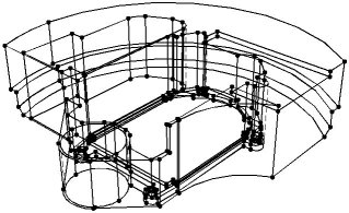
Facets are simply triangles that have been stitched together to form surfaces. Faceted geometry representations are commonly used for graphics, bio-medical, geotechnical and many other applications that output a discrete surface representation. Upon import, the resulting geometry representation is Mesh-Based Geometry. Figure 1. shows an example of a faceted model and the resulting geometry created in CUBIT.


Figure 1. Example of faceted model and the resulting solid model created in CUBIT from the facets.
For convenience, the import facet command currently supports three different formats, facet, AVS and STL
The format for the ASCII facet file is as follows
n m
id1 x1 y1 z1
id2 x2 y2 z2
id3 x3 y3 z3
.
.
.
idn xn yn zn
fid1 id<1> id<2> id<3> [id<4>]
fid2 id<1> id<2> id<3> [id<4>]
fid3 id<1> id<2> id<3> [id<4>]
.
.
.
fidm id<1> id<2> id<3> [id<4>]
Where:
n = number of vertices
m = number of facet
id<i> = vertex ID of vertex i
x<i> y<i> z<i> = location of vertex i
fid<j> = facet ID of facet j
id<1> id<2> id<3> = IDs of facet vertices
[id<4>] = optional fourth vertex for quads
As noted above, the facets can be either quadrilaterals or triangles. Upon import, the facets serve as the underlying representation for the geometry. By default, the facets are not visible once the geometry has been imported. To view the facets, use the following command:
draw surf <id range> facets
The feature angle option is used to specify the angle at which surfaces will be split by a curve or where curves will be split by a vertex. 180 degrees will generate a surface for every facet, while 0 degrees will define a single, unbroken surface from the shell of the mesh. The default angle is 135 degrees. This feature is identical to the feature angle option available when importing Exodus II files.
For the stl format, it is possible to independently control the feature angle for surfaces and curves. If Surface_Feature_Angle is specified, it controls the angle at which surfaces will be split by a curve, while Feature_Angle controls the angle at which curves will be split by a vertex. If Surface_Feature_Angle is not specified, Feature_Angle will control the angle for both surfaces and curves.
This option permits the use of a higher order approximation of the surface when remeshing/refining the resulting geometry. Default is to use the original facets themselves as the curve and surface geometry representation. If the facet model to be imported is to represent geometry with curved surfaces, it may be useful to apply this option. If the Spline option is selected, it will use a 4th order B-Spline approximation to the surface [Walton,96]. More information on using smooth approximation of the facets is available in Importing an Exodus II File.
This option allows the user to either merge or not merge the resulting surfaces. The default option is to merge adjacent surfaces. This results in non-manifold topology, where neighboring surfaces share common curves. The no_merge option, adjacent surfaces will generate distinct/separate curves.
This option creates mesh elements from each of the facets on the facet surface.
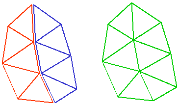
The stitch option is used with the facet or avs format files to try to merge vertices and triangles that are close. Figure 2 shows an example of where this might be employed. The model on the left contains facets that are not connected between the red and blue groups. In this case, the surfaces will not be water-tight, even though the vertices on the boundary between the two groups may be coincident. The stitch option attempts to eliminate the extra edge and vertex between the groups to form the model on the right. This option can be useful when importing facet files for 3D meshing. CUBIT's 3D meshing algorithms require a water-tight (closed) set of surfaces.

Figure 2. Example use of the stitch option on import.
The improve option will collapse short edges on the boundary of the triangulation that are less than 30% the length of the average edge length in the model. In some cases, short edges are the result of discrete boolean operations on the triangulation which may result in edges that are of negligible length. This option is particularly useful for boundaries where multiple surfaces come together at an edge. Figure 3. shows an example of where the improve option improved the quality of the triangles at the boundary. This option is especially useful if the facets themselves will be used for the FEA mesh.
|
Triangles near a boundary that have not been used the improve option |
The same set of triangles where improve option has collapsed edges |
Figure 3. Example use of the improve option