Cubit 16.04 User Documentation
The commands to import meshes from an Exodus II format file are:
Import Mesh '<exodusII_filename>' No_Geom
[Block <block_ids>] [block_name <names>] [{genesis_collision_fail|COMBINE_GENESIS_IDS|combine_genesis_names|unique_genesis_ids}] [block_offset <value>] [sideset_offset <value>] [nodeset_offset <value>] [{node_id_collision_fail|UNIQUE_NODE_IDS}] [{element_id_collision_fail|UNIQUE_ELEMENT_IDS}] [node_offset <value>] [element_offset <value>]] [group_name '<free_elements>'] [[Time <time>|Step <step>|Last] [Scale <value>]]Import Mesh '<exodusII_filename>'
[Block <block_ids>] [block_name <names>] [{genesis_collision_fail|COMBINE_GENESIS_IDS|combine_genesis_names|unique_genesis_ids}] [block_offset <value>] [sideset_offset <value>] [nodeset_offset <value>] [{node_id_collision_fail|UNIQUE_NODE_IDS}] [{element_id_collision_fail|UNIQUE_ELEMENT_IDS}] [node_offset <value>] [element_offset <value>]] [{Group|Body|Volume|Surface|Curve|Vertex} <id_range> | Preview]Import Mesh Geometry '<exodusII_filename>'
[Block <id_range>|ALL] [block_name <names>] [{genesis_collision_fail|COMBINE_GENESIS_IDS|combine_genesis_names|unique_genesis_ids}] [block_offset <value>] [sideset_offset <value>] [nodeset_offset <value>] [{node_id_collision_fail|UNIQUE_NODE_IDS}] [{element_id_collision_fail|UNIQUE_ELEMENT_IDS}] [node_offset <value>] [element_offset <value>]] [Use [NODESET|no_nodeset] [SIDESET|no_sideset] [Feature_Angle <angle>] [Surface_Feature_Angle <angle>] [LINEAR|Gradient|Quadratic|Spline|Acis] [Deformed {Time <time>|Step <step>|Last} [Scale <value>] ] [MERGE|No_Merge] [Merge_nodes <tolerance>]Import Mesh '<exodusII_filename>' Lite
[{genesis_collision_fail|COMBINE_GENESIS_IDS|combine_genesis_names|unique_genesis_ids}] [block_offset <value>] [sideset_offset <value>] [nodeset_offset <value>] [{node_id_collision_fail|UNIQUE_NODE_IDS}] [{element_id_collision_fail|UNIQUE_ELEMENT_IDS}] [node_offset <value>] [element_offset <value>]]
Related Commands:
Import Mesh Geometry (options)
Import Free Mesh (2D)
Delete Mesh Preview
Export [ Genesis | Mesh ] '<filename>'
List Import Mesh NodeSet Associativity
List [Export Mesh] NodeSet Associativity
[Set] Import Mesh NodeSet Associativity [ON|off]
[Set] [Export Mesh] NodeSet Associativity [on|OFF]
Set Import Mesh [Vertex] [Curve] [Surface] Tolerance <distance>
Set Import Mesh NodeSet Order [On|Off]
List Import Mesh NodeSet Order
The Block option in the Import Mesh command indicates that only the specified element block should be imported from the Exodus II file. The blocks are specified by ID. The block_name option can be used to import only the named blocks. Multiple blocks can be imported by making a comma separated list of names. The block and block_name options can be used together to specify some blocks by ID and others by name. If the block or block_name options are not specified, then the entire mesh file is read. These options are not yet supported for lite imports, which currently imports the entire mesh.
The combine_genesis_ids option, is used to combine blocks where the IDs in the session and the file being imported are identical. This can occur when importing into an active session where Cubit IDs have already been assigned. The default behavior is to combine genesis entities based on IDs. If two entities have differnet IDs, but the same names, they will not be combined, and the import will fail.
The combine_genesis_names option, is used to combine blocks where the names in the session and the file being imported are identical. This can occur when importing into an active session where names have already been assigned. If two entities have different names, but identical IDs, they will not be combined, and the import will fail.
The unique_genesis_ids option is used to renumber genesis entities from the genesis file in the case that ID overlap exists when importing into Cubit. The incoming genesis entities are kept unique and are not combined with genesis entities already in the session. In case of colliding IDs, a report displayed in the command window showing the original and new IDs. This renumbering can occur when importing into an active session where Cubit IDs have already been assigned. If an entity being imported has the same name as one already in the session, the entity being imported will be renamed with a number suffix '_N'.
The genesis_collision_fail option allows the user to prevent the genesis file import if any incoming genesis entity IDs or names are already used by genesis entities in the session. This can occur when importing into an active session where Cubit IDs have already been assigned.
The block_offset, sideset_offset, and nodeset_offset options may be used to modify the IDs of genesis entities being imported. The provided value will be added to the ID in the file.
The unique_node_ids, and unique_element_ids options are used to automatically renumber nodes and elements from the genesis file in the case that ID overlap exists when importing into Cubit. If there are no overlaps, the IDs in the file will be preserved. This can occur when importing into an active session where Cubit IDs have already been assigned.
The node_id_collision_fail, and element_id_collision_fail options allows one to prevent the genesis file import if any incoming node or element IDs are already used by mesh entities in the session. This can occur when importing into an active session where Cubit IDs have already been assigned.
The node_offset, and element_offset options may be used to modify the IDs of nodes and elements being imported. The provided value will be added to the ID in the file.
The command to import a free mesh from an Exodus II format file without mesh-based geometry is:
Import Mesh '<exodusII_filename>' No_Geom [group_name '<free_elements>'] [[Time <time>|Step <step>|Last] [Scale <value>]]
When a free Exodus II mesh is imported into Cubit, it contains no geometric or topological information. Previously, the user could either associate that mesh with existing geometry, or build mesh-based geometry to fit the mesh. A third option, as of Cubit 11.1, allows the user to retain the disassociated mesh as a free mesh inside Cubit.
A free mesh may be modified as described in the Free Mesh section of the documentation. This includes limited access to smoothing, renumbering, transformations, refinement, mesh quality, and other mesh centric operations.
When an Exodus II File is imported as a free mesh, Cubit will automatically create a group called "free_elements" to contain the free mesh elements. The 'group_name' option can be used to give the group a different name.
Deformation information can be read in via the Time/Step/Last and Scale parameters.
Note: The Import Mesh <filename> No_Geom command is not to be confused with the Import Free Mesh command which applies only to 2D Exodus II Files.The term "Free Mesh" in both places of the documentation refers to the same thing - a mesh without geometry. However, in the case of all other import mesh commands, the imported free mesh ends up associated with geometry. The Import Mesh <filename> No_Geom is the only way to import a free mesh that remains disassociated from geometry.
The command to import a free mesh from an Exodus II format file and associate it with existing geometry is:
Import Mesh '<exodusII_filename>' [{Group|Body|Volume|Surface|Curve|Vertex} <id_range> | Preview]
The user can import a mesh from an Exodus II file and associate the mesh with matching geometry. The resulting mesh may then be manipulated normally. For example, the mesh may be smoothed or portions of it deleted and remeshed. The user can save their work by exporting the geometry and mesh, and then restore the geometry and mesh later. In some cases, saving and restoring can be faster or more reliable than replaying journal files.
Saving and importing a mesh may be useful for teams working on creating a conforming mesh of a large assembly so that they can pass information to one another. For example, a team member can export the mesh on the surfaces between two parts, and another team member import the mesh for use on an adjoining part of the assembly.
As of cubit version 7.0, any higher order elements, block definitions, nodesets, and sidesets are retained on import.
Meshes can be imported into Cubit that contain nodeset associativity data used for defining finite element boundary conditions. If an exported Cubit mesh is going to be imported back onto the same geometry, then before exporting the user should issue the following command:
set export mesh nodeset associativity on
This causes extra nodeset data to be written, which associates every node to a geometric entity, resulting in an import which is more reliable. When importing, if the user does not want to use the nodeset associativity data that exists in a file, then before importing the following command should be used:
set import mesh nodeset associativity off
The user may wish to turn geometry associativity off if, for example, the geometry is no longer identical as a result of curves being composited, or Cubit names changed due to a ACIS version changes.
Although there are some exceptions, Cubit requires that the mesh be imported onto the same geometry from which it was exported.
Since merge information is not stored with the ACIS representation, care should be taken that the geometry is merged the same way on export and import of the mesh. If not, importing the mesh one block at a time in successive commands may increase the chance of a successful import, at the cost of more memory and time.
Between exporting and importing a mesh, the geometry may be modified slightly by compositing entities. Mesh import will, however not be successful if entities are partitioned or a body is webcut. In some cases mesh import may be successful on modified geometry if the new vertices match up exactly with nodes of the mesh, and the new curves match up exactly with edge chains of the mesh. Unless this criteria is met, associating the mesh with the geometry will be unsuccessful.
To change the tolerance with which imported mesh must line up with geometry issue the command:
Set Import Mesh [Vertex] [Curve] [Surface] Tolerance <distance>
The Block option in the Import Mesh command indicates that only the specified element block should be imported from the Exodus II file. In the same manner, the Volume and other geometry options provide a way to import the nodes and element on the indicated geometry. If neither a block nor a geometry entity is specified, then the entire mesh file is read.
If a block is specified without specifying a geometry entity, associativity or proximity is used to determine which volume the block elements should be associated with. If a block and a volume are specified, the block elements are associated with the specified volume, provided they actually match. If a volume is specified without a block, associativity data is used to find a block corresponding to the given volume.
If the Import mesh NodeSet Order flag is on, the nodesets will be read in a manner which allows them to be associated with existing geometry. This means the nodesets are assumed to be in ascending order. If the flag is set to false, the goemetry nodesets in imported mesh files are assumed to be in random order. This value is on by default, and should not need to be changed by the user.
Cubit's mesh generation tools require an underlying geometry representation. In most cases, the ACIS solid modeling engine, compiled with Cubit, is used to represent the geometry. However, in some cases, an ACIS representation is not available, and a previously developed finite element mesh is the only available representation of the model. In order to utilize Cubit's mesh generation tools, the import mesh geometry command provides an option for creating geometry directly from the finite element mesh.
The import mesh geometry command will create a new volume for every block defined in the Exodus II file. It will also create curves, surfaces and vertices at appropriate locations on the model based on dihedral angles (also called feature angles) and assigned nodesets and/or sidesets. The mesh used to construct the geometry will be owned by the new geometric entities. This means that the mesh can be deleted, remeshed, or smoothed using any of Cubit's meshing tools by simply using the new geometry definition. Cubit will assign appropriate intervals to the new curves as well as determine an acceptable meshing scheme for surfaces and volumes.
The command to import a finite element mesh from an ExodusII format file and generate geometry from the mesh is:
Import Mesh Geometry '<exodusII_filename>'
[Block|ALL] [Use [NODESET|no_nodeset] [SIDESET|no_sideset] [Feature_Angle <angle>] [Surface_Feature_Angle <angle>] [LINEAR|Gradient|Quadratic|Spline|Acis] [Deformed {Time <time>|Step <step>|Last} [Scale <value>] ] [MERGE|No_Merge] [Merge_nodes <tolerance>]
Type the name of file to import in single quotation marks. The file must reside in the current directory. For information on changing the current directory, see Cubit environment commands. To list all the files in the current directory, type ls at the command prompt.
Use this option to select the specific blocks to be imported from the Exodus II file. If no blocks are entered, then all blocks will be read and imported from the file. Standard ID parsing can also be used in this argument to select a range of blocks. For example "1 to 5" or "1, 5 to 10 except 6".
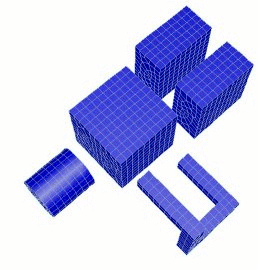
Each unique block selected to be imported will define a new body in the geometric model. Figure 1 shows a simple example of the geometry generated from the 3D finite element mesh.
Figure 1. Example of mesh based geometry (right) created from a finite element mesh (left)
Blocks may be composed of 1D, 2D or 3D elements. For blocks composed of 2D elements (i.e. QUAD4, SHELL etc.), a sheet body will be created. One dimensional elements (i.e.. BEAM, TRUSS, etc.) will define curves. Where a block may be composed of more than one disconnected sets of elements, one body will be created for each continuous region of elements assigned to the same block. Where possible, the ID of the new body will be the same as the block ID. Since IDs must be unique, if a body ID is already in use, the next available ID will automatically assigned by the program.
Use the nodeset and sideset options to use any nodeset and sideset information in the Exodus II file in constructing geometry. Recall that nodesets and sidesets are generic boundary condition data assigned to nodes, edges or faces of the finite elements. It is useful to group mesh entities belonging to unique boundary conditions into geometric entities. This permits the user to remesh a particular region of the model without having to reassign boundary conditions.
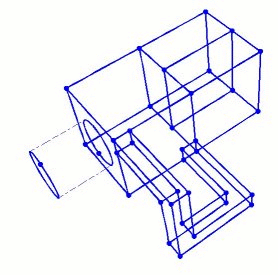
If the nodeset and sideset arguments are given, geometric entities will be generated for each unique set of nodes, edges or element faces assigned to a nodeset or sideset. The default is to use any nodeset and sideset information available in the file. Figure 2 shows an example of how nodeset and sideset information might be used to generate geometry.
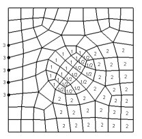
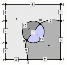
Figure 2. Example of geometry created from mesh entities assigned to nodesets (3) and sidesets (1 and 2).
Upon import, nodesets and sidesets are automatically created with the appropriate geometric entities assigned to them. The IDs of the new geometric entities, if generated from boundary condition data, will be the same as the nodeset and sideset IDs. Where doing so would conflict with existing geometric IDs, the program will automatically select the next available ID.
Use this option to specify the angle at which surfaces will be split by a curve or where curves will be split by a vertex. 180 degrees will generate a surface for every element face, while 0 degrees will define a single, unbroken surface from the shell of the mesh. The default angle is 135 degrees.
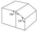
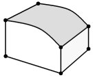
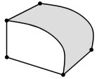
Figure 3. Example use of Feature Angle
Figure 3 shows an example of the use of different feature angles. On the left is a simple two-element hex mesh. Specifying a feature angle greater than 120 degrees would create the geometry in the center image. Using a feature angle less than 120 degrees and greater than 90 degrees would define the geometry on the right.
It is possible to independently control the feature angle for surfaces and curves. If Surface_Feature_Angle is specified, it controls the angle at which surfaces will be split by a curve, while Feature_Angle controls the angle at which curves will be split by a vertex. If Surface_Feature_Angle is not specified, Feature_Angle will control the angle for both surfaces and curves.
This argument allows the option of using a higher-order approximation of the surface when remeshing/refining the resulting geometry. Default is to use the original mesh faces themselves as the curve and surface geometry representation. If the finite element model to be imported is to represent geometry with curved surfaces, it may be useful to select this option. If selected, it will use a 4th order B-Spline approximation to the surface [Walton,96]. Figure 4 shows the effect of the smooth curve and surface option.
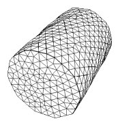
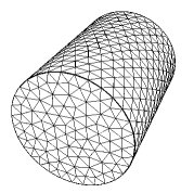
Figure 4. Effect of Smooth Curve and Surface Option for remeshing of mesh-based geometry
In this figure the top image is the original finite element mesh imported into Cubit. In this example both models have been remeshed with the same element size. The difference is that the figure on the right uses the smooth curve and surface option. While this option can improve the surface representation, it should be noted that memory requirements and meshing times can sometimes be affected.
If importing the Exodus II file using the command line, other options for surface representations are also available.
[LINEAR|Gradient|Quadratic|Spline|Acis]
The method used from the GUI is either Linear or Spline. The Gradient and Quadratic methods are still somewhat experimental and may not be as general purpose as the Spline representation. The Acis option will attempt to create ACIS geometry from the mesh. This option is an alpha feature and can only be used if developer commands have been turned on. For more detail see: Acis Geometry From Mesh
This option permits the user to import time-dependant deformation information from the Exodus file. For this option, any vector data in the Exodus II file is assumed to be deformation information. If selected, deformations will be applied to the nodes upon import. Enter a specific time step value, integer step, or the last time available in the file. If time-dependant data is available in the Exodus II file, selecting the down arrow in the edit field will display the available time steps in the file. Default time is the last time step.
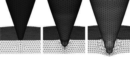
Figure 5. Example of remeshing of a deformed finite element mesh
Figure 5 shows an example of using Mesh-Based Geometry for a large deformation analysis. In this case, the analysis [Attaway et. al.,98] began and continued until mesh quality became unacceptable. At that point, the mesh was imported into Cubit and geometry re-created from the computed deformations. The finite element mesh could then be removed, remeshed or improved and written back to an Exodus II file. After remapping [Wellman,99] the appropriate analysis variables back to the mesh, the analysis could then be restarted. This process was repeated multiple times until the desired results were achieved.
Note: Care should be taken when using large deformations, as inverted elements (negative Jacobians) may produce unpredictable results with the resulting geometric representation.
Also available is an optional scale factor. This applies the indicated scale to all deformations. Default is 1.0.
This option allows the user to either merge or not merge the resulting volumes. The default option is to merge adjacent volumes. This results in non-manifold topology, where neighboring volumes share common surfaces. Using the no_merge option, adjacent volumes will generate distinct/separate surfaces.
The merge_nodes option will allow the user to specify a different tolerance for merging nodes on import. The default value is 1e-6.
Note: Care should be taken when setting import merge tolerances. Setting a tolerance too low will not merge adjacent nodes. Setting the tolerance too high can produce undesirable results, and severely tangle the mesh.
The command to import a lite mesh from an Exodus II format file is:
Import Mesh '<exodusII_filename>' lite
When an Exodus II mesh is imported into Cubit using the lite option, it contains no geometric or topological information.
The lite mesh import may be an option for users wanting to quickly view the mesh without gaining all the abilities to modify the mesh.
More information on how a lite mesh may be viewed or modified is described in the Lite Mesh section of the documentation.