Cubit 16.02 User Documentation
The following options of the Tweak Surface command are available. Command syntax and examples follow below.
Tweak Surface <id_list> Offset <val> [Surface <id_list> Offset <val>] [Surface <id_list> Offset <val> ...] [Keep] [Preview]
The Tweak Offset form of the command offsets an existing set of surfaces and extends the attached surfaces to meet them. A positive offset value will offset the surface in the positive surface normal direction while a negative value will go the other way. Different offsets may be specified for each surface. Figure 1 shows a simple example of offsetting. Note that you can also offset whole groups of surfaces at once. The keep option will retain the original surfaces and curves.
Figure 1. Tweak Offset
The Tweak move form of the command simply moves the given surfaces along a vector direction. The direction can be specified either absolutely or relative to other geometry entities in the model (from entity centroid to location). Note that when moving a surface for tweak, the surface is moved and the surface and the adjoining surfaces are extended or trimmed to match up again. So, for example, moving a vertically oriented planar surface in the vertical direction will have no effect. In this example, if you move the surface 10 in the x and 5 in the y the effect will be to move it simply 10 in the x. You can also use this form of the command to move a protrusion around - just be sure to specify all of the surfaces on the protrusion for moving. The last form of the command can be used to move a surface along another surface's normal.
Tweak Surface <id_range> Move {Vertex|Curve|Surface|Volume|Body} <id> Location {Vertex|Curve|Surface|Volume|Body} <id> [Except [X][Y][Z]] [Keep] [Preview]
Tweak Surface <id_range> Move {Vertex|Curve|Surface|Volume|Body} <id> Location <x_val> <y_val> <z_val> [Except [X][Y][Z]] [Keep][Preview]
Tweak Surface <id_range> Move <dx_val> <dy_val> <dz_val> [Keep] [Preview]
Tweak Surface <id_range> Move Direction <options> Distance <val> [Keep] [Preview]
Tweak Surface <id_range> Move Normal To Surface <id> Distance <val> [Except [X][Y][Z]] [Keep][Preview]
The Tweak target form of the command actually replaces the given surfaces with a copy of the new surfaces, then extends and trims surfaces to match up. This can be useful for closing gaps between components or performing more complicated modifications to models. The command syntax is:
Tweak {Curve|Surface} <id_list> Target {Surface <id_list> [Limit Plane (options)] [EXTEND|noextend] | Plane (options)} [keep] [preview]
Tweak Surface <id_list> Replace [With] Surface <id_list> [Keep] [Preview]
The plane option allows a plane to be specified instead of target surface(s). If a target surface is supplied, the user can also use a limit plane if he wishes. A limit plane is a plane that the tweak will stop at if the tweaked surface does not completely intersect the target surface. The limit plane must be used with the extend option. See the help for Specifying a Plane for the options available to define a plane.
Single target surfaces are automatically extended so that the tweaked body will fully intersect the target. Unfortunately, extending multiple target surfaces can sometimes result in an invalid target, so the option is given to tweak to unextended targets with the noextend option. In this case, the tweaked body must fully intersect the existing targets for success. If you experience a failure when tweaking to multiple targets or the results are unexpected, it is recommended to try the noextend option (NOTE: Tweaking to multiple targets is only implemented in the ACIS geometry engine). It is recommended to always preview before using the tweak target commands.
Figure 2 shows a simple example.
Figure 2. Tweak Surface Target (Viewed directly from the side)
The Tweak remove command allows you to remove surfaces from a model by extending the adjacent surfaces to fill in the resulting gaps. It is identical to the Remove Surface command. See Removing Surfaces for a description of the command options.
Tweak Surface <id_list> Remove [Blend_Chain] [Cavity] [EXTEND|Noextend] [Keepsurface] [Keep] [Preview]
The Tweak cone form of the command is used to replace a conical projection with a flat circular surface. This command is useful for simplifying bolt holes. The command syntax is.
Tweak Surface <id_range> Cone [Preview]
The following is a simple example illustrating the use of the tweak surface cone command.
Figure 3. Conical bolt hole before and after tweaking
The Tweak Doubler form of the command takes a specified surface and creates drop-down surfaces either normal to the doubler surface or by a user specified vector to a target surface. This can be helpful in creating surfaces for weld elements between midsurfaced geometry. The resulting surfaces do not create a bounding volume, and do not imprint themselves onto the target surface. The command syntax is:
Tweak Surface <id_list> Doubler Surface <id_list> {[Limit Plane (options)] [EXTEND|noextend]} [Internal] [Direction (options)] [Thickness] [Preview]
The plane option allows a plane to be specified instead of target surface(s). If a target surface is supplied, the user can also use a limit plane if he wishes. A limit plane is a plane that the tweak will stop at if the tweaked surface does not completely intersect the target surface. The limit plane must be used with the extend option. See the help for Specifying a Plane for the options available to define a plane.
Single target surfaces are automatically extended so that the tweaked body will fully intersect the target. Unfortunately, extending multiple target surfaces can sometimes result in an invalid target, so the option is given to tweak to unextended targets with the noextend option. In this case, the tweaked body must fully intersect the existing targets for success. If you experience a failure when tweaking to multiple targets or the results are unexpected, trying the noextend option is recommended.
If the doubler surface has a thickness property value, you can propagate that thickness value to the newly created drop-down surfaces by using the thickness flag.
It is recommended to always preview before using the tweak doubler commands.
NOTE: This function only works for ACIS geometry.
 |
 |
Geometry |
Output |
Figure 3. Extending a doubler surface to target
The internal option will also include internal curves when the surface is extended (see Figure 4c). The direction option will create a skewed surface along the given direction (see Figure 4d).
Figure 4. Explanation of tweak doubler options (a) Original surfaces (b) No option flags used (c) Internal option used - notice internal curves dropped down (d) Direction flag - notice skew
The Tweak Hole/Slot Idealize command takes a specified sheet body(s) and searches for either holes or slots (or both) which meet the user's input parameters. This can be helpful in removing small holes or slots quickly and efficiently from midsurfaced bodies where such level of detail isn't required. The command syntax is:
Tweak Surface <id_list> Idealize {[Hole Radius <val>] [Slot Radius <val> Length <val>]} [Exclude Curve <id_list>] [Preview]
Below is a diagram showing the different parameters available for input by the user.
Figure 5. Input parameters for tweak surface idealize command
#Hole Removal Example
tweak surface 13 idealize hole radius 6
Figure 6. Example of hole removal using tweak surface idealize command
The exclude option allows the user to specify individual curves that should not be deleted, even if they meet the search criteria for removal. Figure 7 shows another hole removal example where several curves were excluded.
Figure 7. Example of hole removal using exclude option
Note: This feature is for ACIS geometry
It is recommended to always preview before using the tweak command. Preview will highlight all curves slated to be removed if the command is executed.
The Tweak Fillet Idealize command takes a specified sheet body(s) and searches for either internal or external fillets (or both) which meet the users' radius parameter. This can be helpful in removing fillets quickly and efficiently from midsurfaced bodies where such level of detail isn't required. The command syntax is:
Tweak Surface <id_list> Idealize Fillet Radius <val> {[Internal] [External]} [Exclude Curve <id_list>] [Preview]
#Fillet Removal Example
tweak surface 13 idealize fillet radius 6 internal
Figure 8. Example of fillet removal using tweak surface idealize command
Note: This feature is for ACIS geometry
It is recommended to always preview before using the tweak command. Preview will show the result if the command is executed.
Figure 9. Preview of the tweak surface idealize command
The taper or angle of a surface can be made shallower or steeper using the taper surface command. Several surfaces can be tapered at once to get a smooth transition. The command syntax is:
taper Surface <id_list> angle <val> {from plane <options> | about curve <id> | about vertex <id_1><id_2>} [keep] [preview]
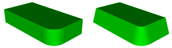
Figure 10. taper surface 1 7 6 angle -20 from plane surface 3
The keep and preview options are helpful when figuring out the correct command setup.
The from plane form of the command is the most basic form of the command. The plane normal defines the direction used to set the angle for the surface. The origin of the plane determines how a surface is tapered. If the plane intersects the middle of a surface, the surface will be rotated in on the top and out on the bottom. If it intersects the bottom, the top of the surface will be rotated in and the bottom will stay fixed. If it intersects the top, the bottom of the surface will rotate out and the top will stay fixed.
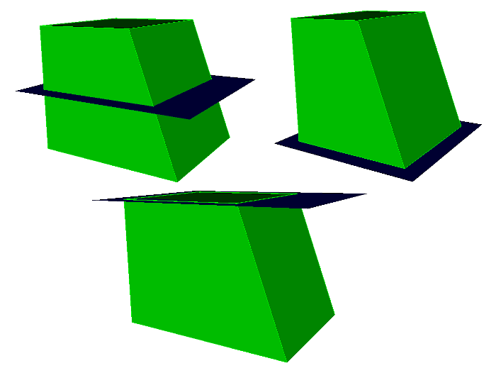
Figure 11. A cube with one surface tapered 20 degrees with a plane in the middle, bottom, and top.
The about curve form of the command can be used to rotate a surface about a curve. The axis of rotation is determined using the tangent direction of the curve at its starting point. That axis crossed with the normal of the surface at the starting point determine the direction used to set the surface angle. In order to work, the curve must be part of one of the surfaces being changed. Since the direction is based on the curve sense, the final direction is not always obvious. Running the command with the preview option first can help determine what angle to apply.
The about vertex form of the command is similar to the about curve form. The axis of rotation is a vector from the first vertex to the second. That axis crossed with the normal of the surface at the starting point determine the direction used to set the surface angle. In order to work, the vertices must be part of one of the surfaces being changed.