Cubit 15.8 User Documentation
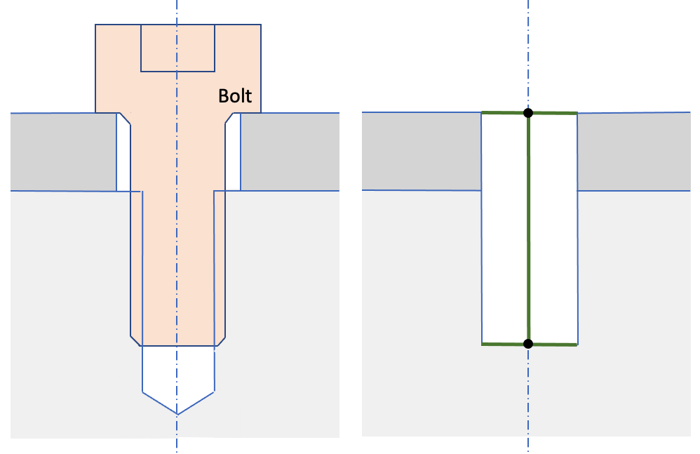
The Reduce Bolt command is intended to prepare a volume identified as a bolt for analysis by simplifying its geometry, fitting to overlapping geometry, creating blocks and groups, etc. For the spider option of the reduce command, the bolt will be deleted and replaced with a beam mesh. There are currently three different options for the spider command as illustrated in figures 1 to 3.
Figure 1. Example before and after of the Reduce Bolt Spider Wagon_Wheel command
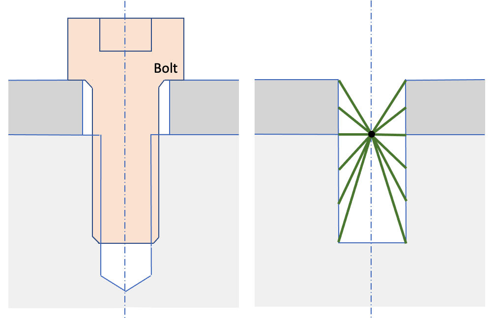
Figure 2. Example before and after of the Reduce Bolt Spider J2G command
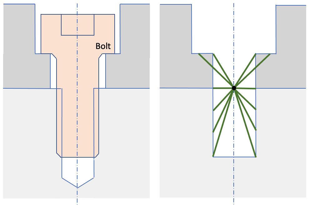
Figure 3. Example before and after of the Reduce Bolt Spider Countersink command
Syntax:
Reduce volume {<ids>} bolt spider {wagon wheel|j2g|countersink}
[diameter <value>] [mesh_spider] [increment_block_ids]
[spider_block_id {<value>|Default}] [spider_block_name {<string>|Default}]
[rebar_block_id {<value>|Default}] [rebar_block_name {<string>|Default}]
[preview]
Discussion:
The spider options will also simplify the surrounding geometry at the hole, including removing any blends or chamfers. It will also simplify the hole so in the lower volume to which the bolt is fastened will be fit exactly to the bolt geometry.
The spider options will not, by default, generate the beam mesh as shown in figures 1 to 3, but instead define blocks to which the beam elements will be added when the mesh is generated. The following describes the options for the reduce bolt spider command.
volume ids: Specify the ids of the volumes to be reduced. The Geometry Power Tool classification diagnosic can be used for identifying volumes as "bolts".
{wagon wheel|j2g|countersink}: One of these three methods must be specified for the spider option.
diameter <value>: Use the diameter option to alter the diameter of the resulting hole. If no value is specified for diameter, the existing diameter of the bolt will be used.
mesh_spider: This option can be used to generate the beam mesh as part of the reduce operation. Since the resolution of the beam mesh depends on the nodes defined on the hole geometry, the surfaces of the hole will also be meshed using a mapped meshing scheme. The mesh size defined on the volume will be used for meshing. If no mesh size has been defined, an automatic default size will be computed and used for meshing. Note that if the mesh_spider is not used, an empty spider and rebar block will be generated. When the hole surfaces are meshed, the beam elements will also be generated and assigned to the existing spider and rebar blocks
The spider and rebar blocks may be defined by either a block_name or block_id. If the block does not yet exist, a new one will be created. The Default option will automatically select an id or name. The default names for the spider and rebar blocks are Spider_Block and Rebar_Block respectively.increment_block_ids: When building new blocks for each bolt volume, the block IDs can be automatically generated by incrementing from a specified block_id. For example, if rebar_block_id is defined as 100, and the increment_block_ids option is used, each new rebar generated will be assigned to a new unique block id starting with 100, followed by 101, 102, 103, etc.
preview: optional argument to display a preview of the spider operation without execution of the reduction. This option will display the proposed beam mesh with the surrounding volumes displayed in wireframe.