To model adhesives, interfaces in composite
materials or crack propagation, it is possible to create cohesive
elements.
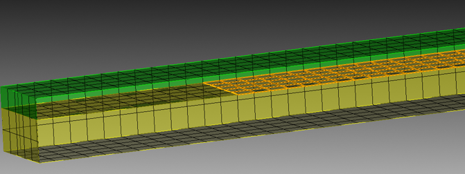
A geometry with highlighted surface indicating location for
cohesive elements
The above example has a shared surface between the green and
yellow volumes which is already cracked, using the unmerge
command in Cubit. The highlighted merged surface can then used
for creating cohesive elements. The following command will do so.
Create Cohesive Elements Block <value>
Surface <ids>
The Block keyword
indicates the block id for the newly created block.
The Surface keyword
indicates which surfaces to unmerge and insert cohesive
elements..
Creating cohesive elements is supported for both hex an tet meshes.
In the case of hex meshes, the resulting cohesive elements are also hexes.
In the case of tet meshes, the resulting cohesive elements are wedges.
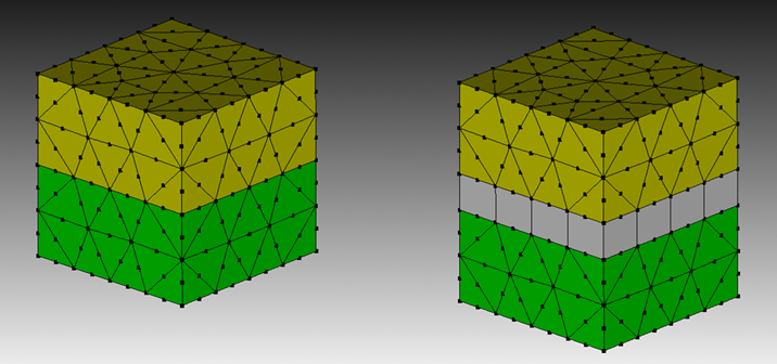
For a basic tetra4 mesh, the resulting CSEs are wedge6 elements. For a higher
order tetra10 mesh, the resuling CSEs are wedge12 elements. The extra 6 mid-edge nodes
are on the top and bottom triangular faces to match up with the neighboring tetra10 elements.
See the following image for an illustration of how wedge12 CSEs are inserted, with wedges
being stretched for illustration purposes. Normally, they are flat.
A geometry (on left) with CSEs inserted (on right). Note, wedge12 elements
are stretched for illustration purposes.
Creating cohesive elements on free mesh is also supported. This allows creation
of CSEs when geometry is absent or when construction of geometry is not necessary.
Create Cohesive Elements Block <value> [Tri <ids>] [Face <ids>]
Triangles or Faces or both can be supplied for locations to insert CSEs. When multiple triangles
and/or faces are given, they are inspected to ensure insertion of CSEs will succeed and that no invalid
topology will result. If an insertion will result in invalid topology, the insertion will be disallowed.
For convenience, one can use groups or sidesets to supply a list of triangles or faces.