Cubit
17.02
User Documentation![]()
Cubit
17.02
User Documentation![]()
Summary: Creates a free cylindrical mesh with precise node locations based on input radii, angles, and offsets, then creates mesh-based geometry to fit the mesh.
Syntax:
Create Radialmesh \
NumZ <val> [Span <val>] \
Zblock 1 [<offset val>] \
{Interval|Bias|Fraction|First Size} <val> \
[{Interval|Bias|Fraction|Last Size} <val>] \
Zblock 2 [<offset val>] \
{Interval|Bias|Fraction|First Size} <val> \
[{Interval|Bias|Fraction|Last Size} <val>] \
... NumZ \
NumR <val> {Trisection|Initial Radius<val>} \
Rblock 1 <offset radius val> \
{Interval|Bias|Fraction|First Size} <val> \
[{Interval|Bias|Fraction|Last Size} <val>] \
Rblock 2 <offset radius val> \
{Interval|Bias|Fraction|First Size} <val> \
[{Interval|Bias|Fraction|Last Size} <val>] \
... NumR \
NumA <val> [Full360] [Span <val>] \
Ablock 1 [<offset angle val>] \
{Interval|Bias|Fraction|First Angle} <val> \
[{Interval|Bias|Fraction|Last Angle} <val>] \
Ablock 2 [<offset angle val>] \
{Interval|Bias|Fraction|First Angle} <val> \
[{Interval|Bias|Fraction|Last Angle} <val>] \
... NumA
Discussion:
The purpose of the radialmesh command is to create a cylindrical mesh with precise node locations. Unlike all other meshing commands which place nodes using smoothing algorithms to optimize element quality, node locations for the radialmesh command are calculated based on the input radii, angles, and offsets. In addition, the radialmesh command does not mesh existing geometry. Rather, it creates a mesh based on the input parameters, after which a mesh-based geometry is created to fit the free mesh.
The radialmesh command requires input for the 3 coordinate directions (Z, radial, angular). The number of blocks in each direction is specified with the numZ, numR, and numA values in the command. Each block forms a new volume in the final mesh. All bodies in the mesh are merged to form a conformal mesh between blocks.
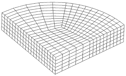
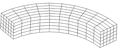
The Radialmesh command can create meshes which span any angle greater than 0.0 up to 360 degrees. In addition, meshes can model either a tri-section (see Figure 1), or a non-trisection mesh (see Figure 2).

Figure 1. Tri-section Radialmesh

Figure 2. Non-tri-section Radialmesh
The command to generate the mesh in Figure 1 is:
create radialmesh \
numZ 1 zblock 1 1 interval 5 \
numR 3 trisection rblock 1 2 interval 5 \
rblock 2 3 interval 5 \
rblock 3 4 interval 5 \
numA 1 span 90 ablock 1 interval 10
The command to generate the mesh in Figure 2 is:
create radialmesh \
numZ 1 zblock 1 1 interval 5 \
numR 1 initial radius 3 rblock 1 4 interval 5 \
numA 1 span 90 ablock 1 interval 10
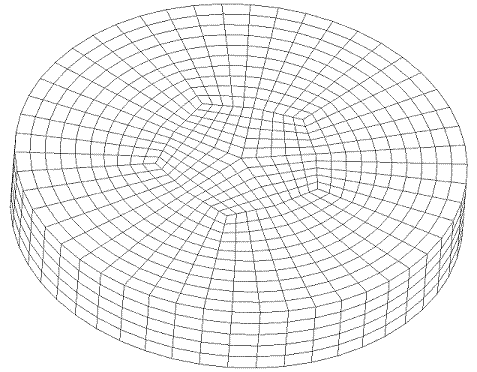
A mesh can span an entire 360 degrees by using the “full360” keyword. For example, the mesh in Figure 3 was generated with the following command:
create radialmesh numZ 1 zblock 1 1 interval 5 \
numR 3 trisection rblock 1 1 interval 5 \
rblock 2 2 interval 5 \
rblock 3 3 interval 5 \
numA 5 full360 span ablock 1 interval 5 \
ablock 2 interval 5 \
ablock 3 interval 5 \
ablock 4 interval 5

Figure 4. Radialmesh using full360 option
After the mesh is generated, the radialmesh command fits the mesh with mesh based geometry. The surfaces created to fit the mesh are given special names according to their location on the geometry. To see the names of the surfaces, issue the command label surface name after creating a radialmesh. Also, if you create a tri-section mesh, the edges on the center axis are given names. To see these names issue the command label curve name after creating a trisection Radialmesh.
The user can control the number of intervals and the spacing of these intervals using the optional parameters in each rblock, zblock and ablock. There are 11 combinations that these can be combined as listed below:
Interval Only- Example: "interval 5." The block will be meshed with 5 equally spaced intervals.
First Size Only- Example: “first size 2.5.” The block will be meshed with intervals of approximately 2.5 in length. The total number of intervals is internally calculated and depends on the overall block length.
Fraction Only- Example: “fraction 0.3333.” The block will be meshed with intervals approximately 0.3333*overall block length.
Interval and Bias- Example: “interval 5 bias 1.5.” There will be 5 intervals on the block, which each interval being 1.5 times the previous one. The length of each interval is calculated internally.
Interval and Fraction- Example: “interval 5 fraction 0.25.” There will be 5 intervals on the block, the first being .25 of the length of the block with the remaining decreasing in size.
Interval and First Size- Example: “interval 5 first size 0.2.” There will be 5 intervals on the block, the first being 0.2 in length. The remaining intervals will increase or decrease to fill the blocks length.
First Size and Last Size- Example: “first size 0.2 last size 0.4.” The first interval will be 0.2 in length. The last interval will be 0.4 in length. The total number of intervals is internally calculated to allow for transition between the 2 specified sizes.
First Size and Bias- Example “first size 0.2 bias 0.85.” The first interval will be 0.2 in length and the remaining intervals will scale by a factor of 0.85 from one to the next until the block is filled. The total number of intervals is internally calculated and depends on the overall block length.
Fraction and Bias- Example “fraction 0.25 bias 1.25.” The first interval will be 0.25 of the overall block length and the remaining intervals will scale by a factor of 1.25 from one to the next until the block is filled. The total number of intervals is internally calculated and depends on the overall block length.
Interval and Last Size- Example: “last size 1.5 interval 5.” The last interval will be 1.5 in length. The remaining intervals will scale up or down to fit 5 intervals in the block.
Last Size and Bias- Example: “last size 2.0 bias 1.1.” The last interval will be 2.0 in length. The remaining intervals will scale by 1.1 until the block is filled. The total number of intervals is internally calculated and depends on the overall block length.
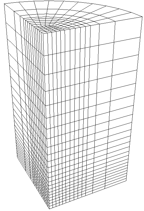
Figure 5 shows an example of a bias spaced mesh with the following command:
create radialmesh numZ 2 zblock 1 1 first size 0.2 \
zblock 2 10 first size 0.2 last size 1.0 \
numR 3 trisection rblock 1 1 interval 5 \
rblock 2 2 first size .25 \
rblock 3 5 first size .25 bias 2.0 \
numA 1 span 90 ablock 1 interval 5

Figure 5. Radialmesh created with biased spacing
![]()