Cubit 16.14 User Documentation
The Reduce Bolt command generates a proxy representation of a bolt for analysis. It replaces the bolt geometry with two concentric circular surfaces centered on the bolt axis, separating the connected volumes where sidesets are automatically applied.
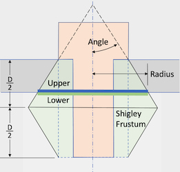
Figure 1. Example of the Reduce Bolt Patch command. The Shigley frustum is used to calculate the diameter of the sidesets positioned between the volumes.
Syntax:
Reduce {volume <ids>|upper surface <ids> lower surface <ids>} {bolt|hole} patch [contact upper {surface <ids>}] [contact lower {surface <ids>}] [radius {<value>|Factor <value>|SHIGLEY [angle {<value>}]}] [mesh] [mesh_size <value>] [mesh_scheme <string>] [{FILL|no_fill}] [{DELETE|no_delete}] [upper_patch_sideset_id {<value>|Default}] [increment_upper_patch_sideset_id] [start_upper_sideset_id {<value>|Default}] [upper_patch_sideset_name {<string>|Default}] [lower_patch_sideset_id {<value>|Default}] [increment_lower_patch_sideset_id] [start_lower_sideset_id {<value>|Default}] [lower_patch_sideset_name {<string>|Default}] [name_patch_surfaces] [preview]
Discussion:
The Reduce Bolt Patch command is often used in structural dynamic applications to replace bolts or bolt holes with concentric circular sidesets attached to the upper and lower volumes. If the specified radius exceeds surface bounds, clipping occurs. The resulting circular surfaces are automatically assigned to customizable sidesets. The patch radii are determined using the default Shigley frustum angle, as illustrated in Figure 1. Users can modify the Shigley angle or set the diameter explicitly as an absolute value or a factor of the shank radius. The command also supports automatic meshing of the sidesets with a user-defined scheme and size.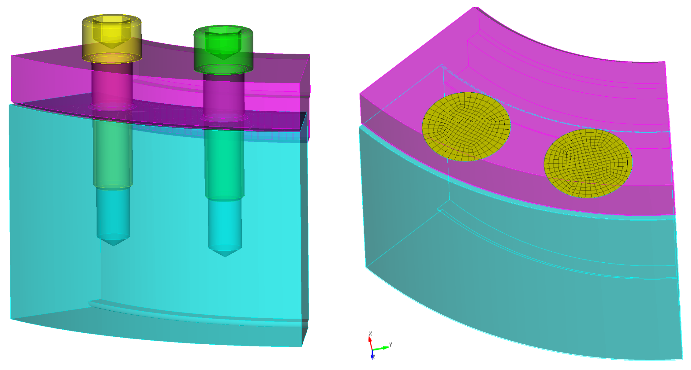
Figure 2. Example of before and after where the reduce bolt patch command has been applied to two bolts. This example uses the mesh and default fill and delete options.
The following outlines the options for the reduce bolt patch command.
You can input either the ID of the bolt to be reduced or the IDs of holes intended for fasteners if no bolt volume is present. Choose between the bolt or hole options based on your specific needs.
bolt
volume <ids>: Specify the ids of the volumes to be reduced. The Geometry Power Tool classification diagnosic can be used for identifying volumes as "bolts".
hole
upper surface <ids> lower surface <ids>: Specify hole IDs for fastener reduction, including at least one surface from both upper and lower holes. Cubit checks axis alignment and matches multiple holes if specified. For more than two fastened volumes, Cubit supports up to three; designate the topmost with >upper surface and the rest with lower surface.
contact upper {surface <ids>} contact lower {surface <ids>}: In rare cases, the reduce patch command may not auto-identify upper and lower contact surfaces. If this occurs, you can manually specify these surfaces to resolve the issue. Note: This option is only available for a single bolt or hole set.
radius {<value>|Factor <ids>|SHIGLEY [angle {<ids>}]}
radius <value>: The Reduce Bolt Patch allows you to directly set the radius by specifying a floating-point value. Use this option to set an absolute value for the sideset radius on the contact surfaces. This value will determine the radius of the resulting imprinted circle where the sideset is defined.
radius factor <value>: The radius factor option allows you to define the radius of the resulting imprinted circle as a multiple of the shank bolt's radius. If no bolt is present and only the hole is specified, the radius will be a multiple of the upper hole's radius.
radius shigley angle <value>: The radius shigley angle option is the default method for determining the radius. It employs a Shigley angle, as outlined in SAND2008-0371 (Figure 1). If no radius specification is provided, the Shigley angle defaults to 30 degrees to compute the radius. This radius is determined by the intersection of the frustum with the surface between the upper and lower volumes.
The circular patch size can vary based on several factors, such as the thickness of the upper volume, the radius of the bolt head, and the length of the bolt. For more comprehensive details, refer to the SANDIA REPORT SAND2008-0371, "Guideline for Bolted Joint Design and Analysis: Version 1.0."
Note: The radius shigley angle option is applicable only when a bolt is specified. If no bolt is present and only the holes are specified, and no radius is given, the radius factor option becomes the default. In such cases, a default factor of 2.5 will be used to compute the radius.
The Reduce Bolt Patch command imprints concentric circular patches onto the surfaces of the upper and lower volumes. If the surfaces on the upper and lower volume do not extend beyond the specified radius, the resulting surfaces will be clipped accordingly.
mesh: Option to specify whether to include meshing as part of the command.
mesh_size <value>: Optionally specify a target mesh size when using the mesh
mesh_scheme <string>: Specify a target meshing scheme. The following meshing schemes can be used for this operation:
FILL|no_fill: The FILL|no_fill option controls hole treatment. By default setting, FILL removes the hole entirely, along with any features like fillets. The no_fill option retains the hole but simplifies it, removing fillets and creating an annulus centered on the hole's axis. The annulus diameter is set by one of the radius options.
DELETE|no_delete: The default behavior of this command is to delete the bolt as part of the operation. However, users have the flexibility to choose whether or not to delete the bolt.Optional increment and start_id arguments are available for both upper and lower sideset ID specifications. When used, these options automatically generate incrementing sideset IDs. For example, if lower_patch_sideset_id is set to 100 and increment_lower_patch_sideset_id is used, new bolt patches will have unique sideset IDs starting from 100 (e.g., 101, 102, 103). If both upper_patch_sideset_id and start_upper_sideset_id (or their lower counterparts) are used with increment, the new patches may be added to the existing sideset and a new, incrementing sideset, effectively adding the same patch to two different sidesets.
name_patch_surfaces: This option allows you to name the surfaces created by the reduce patch command. You can use either default or custom names. Default names are "Upper_Patch" and "Lower_Patch". If you specify names using upper_patch_sideset_name or lower_patch_sideset_name, those names will instead be applied to the resulting circular surfaces. This is helpful for referencing in future scripts or journal commands.