Cubit 16.14 User Documentation
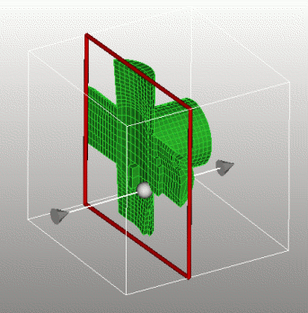
The graphics clipping plane feature allows the user to temporarily cut parts of the model away to help visualize the interior of a geometry or mesh. The command syntax is:
The GUI tool bar buttons to enable and manipulate the Graphics Clipping Plane are shown below:Graphics Clip {On|Off} [ Plane <plane> | [Location <location>] [Direction <direction>]]
Graphics Clip Manipulation {On|Off}
![]()

Figure 1. Graphics Clipping Plane
The second command turns on/off the visibility of manipulation widget in the graphics window. The clipping plane is still active, but the controls are hidden. The normal mouse-based view navigation controls apply.
brick x 10
sphere rad 1
graphics clip on location -2 0 0
rotate -45 about y
#shows the sphere inside the brick
brick x 10
cylinder rad 2 z 12
subtract 2 from 1
mesh vol 1
quality vol 1 draw mesh
graphics clip on
#shows the mesh quality on interior elements

Figure 2. Viewing mesh quality of interior elements