Cubit 16.12 User Documentation
The Reduce Bolt command generates a proxy representation of a bolt for analysis. It replaces the bolt geometry with two concentric circular surfaces centered on the bolt axis, separating the connected volumes where sidesets are automatically applied.
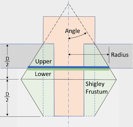
Figure 1. Example of the Reduce Bolt Patch command. The Shigley frustum is used to calculate the diameter of the sidesets positioned between the volumes.
Syntax:
Reduce {volume <ids>} bolt patch [radius {<value>|SHIGLEY [angle {<value>}]}] [mesh] [mesh_size <value>] [mesh_scheme <string>] [{FILL|no_fill}] [{DELETE|no_delete}] [upper_patch_sideset_id {<value>|Default}] [increment_upper_patch_sideset_id] [upper_patch_sideset_name {<string>|Default}] [lower_patch_sideset_id {<value>|Default}] [increment_lower_patch_sideset_id] [lower_patch_sideset_name {<string>|Default}] [preview]
Discussion:
The Reduce Bolt Patch command is widely used in structural dynamic applications. It replaces bolts with concentric circular sidesets, one attached to the upper volume and another to the lower volume. If the specified radius exceeds the surface bounds, clipping is applied accordingly. The resulting circular surfaces are automatically assigned to customizable sidesets. The patch radii are determined using the default Shigley frustum angle (Figure 1), but users can modify the Shigley angle or explicitly set the diameter. Moreover, this command facilitates automatic meshing of the sidesets with a user-defined scheme and size.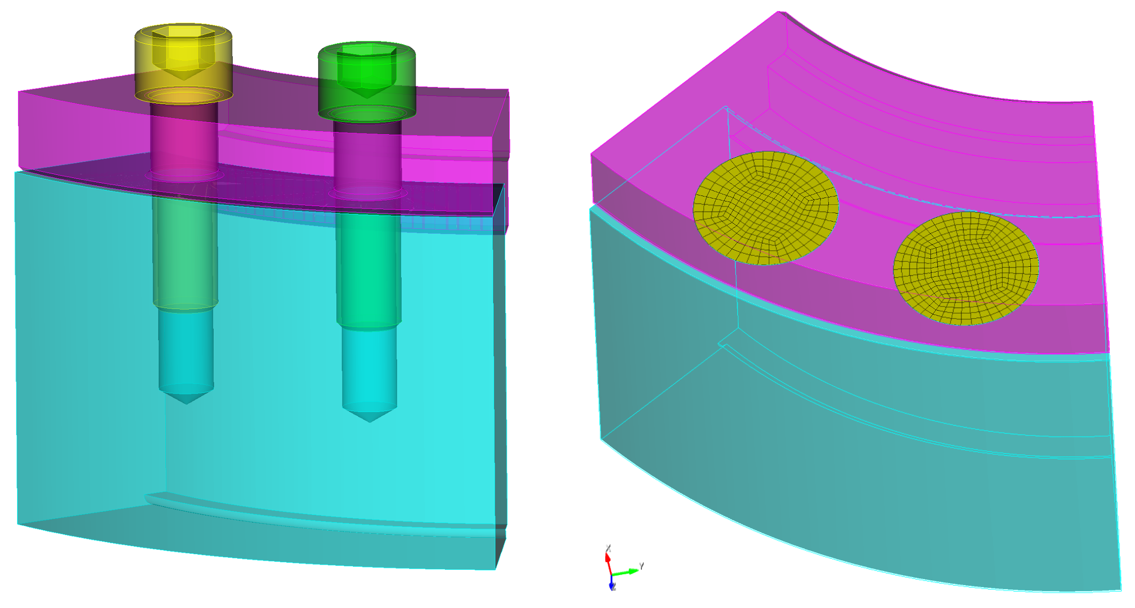
Figure 2. Example of before and after where the reduce bolt patch command has been applied to two bolts. This example uses the mesh and default fill and delete options.
The following outlines the options for the reduce bolt patch command.
volume ids: Specify the ids of the volumes to be reduced. The Geometry Power Tool classification diagnosic can be used for identifying volumes as "bolts".
radius {<value>|SHIGLEY [angle {<value>}]}: The Reduce Bolt Patch command provides the option to define the radius directly by specifying a floating-point value. By default, the command uses the Shigley radius as defined in the reference SAND2008-0371 (Figure 1). The circle is defined by a frustum with its axis aligned with the bolt's axis. The frustum passes through the outer diameter of the bolt head where it meets the top of the upper volume. The Shigley angle refers to the angle between the bolt axis and the conical surface passing through the outer diameter of the head (Figure 1). The radius of the patches is determined by the intersection of the frustum with the surface interface between the upper and lower volumes. The maximum radius is defined as half the length of the bolt shaft (Figure 1).
In general, a larger Shigley angle results in a larger radius, while a smaller angle yields a smaller radius. The reference suggests a default value of 30 degrees for the Shigley angle. The size of the circular patches varies depending on the thickness of the upper volume, the radius of the bolt head, and the length of the bolt.
For detailed calculations and further information, please refer to the SANDIA REPORT, SAND2008-0371, titled "Guideline for Bolted Joint Design and Analysis: Version 1.0" by Kevin H. Brown, Charles Morrow, Samuel Durbin, and Allen Baca.
The Reduce Bolt Patch command imprints concentric circular patches onto the surfaces of the upper and lower volumes. If the surfaces on the upper and lower volume do not extend beyond the specified radius, the resulting surfaces will be clipped accordingly.
When the no_fill option is used, an annulus is defined instead of a complete circle. The center circle of the annulus corresponds to the diameter of the hole.
mesh: Option to specify whether to include meshing as part of the command.
mesh_size <value>: Optionally specify a target mesh size when using the mesh
mesh_scheme <string>: Specify a target meshing scheme. The following meshing schemes can be used for this operation:
FILL|no_fill: By default, the "FILL" option removes the hole in the upper and lower volumes where the bolt is located. If the hole is retained, it will be simplified by removing fillets and conical surfaces at its base. Alternatively, selecting the "no_fill" option defines an annulus centered on the bolt axis, instead of a complete circle.
DELETE|no_delete: The default behavior of this command is to delete the bolt as part of the operation. However, users have the flexibility to choose whether or not to delete the bolt.
Sideset ID and name assignment: The following options may be used to assign the resulting circular surfaces based on an ID or a sideset name:
Each of the sideset ID specifications for upper and lower also have a corresponding optional increment argument. When generating new bolt patches, the sideset ID can be automatically generated by incrementing from a specified sideset_id. For example, if lower_patch_sideset_id is defined as 100, and the increment_lower_patch_sideset_id option is used, each new bolt patch generated will be assigned to a new unique sideset id starting with 100, followed by 101, 102, 103, etc.