 Figure 1. The procedure for generating a hex mesh
using the Sculpt overlay grid method
Figure 1. The procedure for generating a hex mesh
using the Sculpt overlay grid methodCubit 16.10 User Documentation
This document provides a brief technical overview of the Sculpt application, a separate companion application to Cubit designed to generate all-hex meshes of complex geometries. Details on command arguments to Sculpt may be found here. Also information for using Cubit to set up input for Sculpt may be found here.
The method for generating an all-hex mesh employed by Sculpt is often referred to in the literature as an overlay-grid or mesh-first method. This differs significantly from the algorithms employed by Sweeping and Mapping, which are classified as geometry-first methods. Mapping and Sweeping start with the geometry, carefully fitting logical groupings of hexes to conform to a recognized topology. In contrast, the Sculpt method begins with a base Cartesian grid encompassing the geometry which is used as the basis for the mesh. Geometric features are carved or sculpted from the Cartesian grid and boundaries smoothed to create the final hex mesh. The obvious benefit of the Sculpt (mesh-first) method over Mapping and Sweeping (geometry-first) methods is there is no need to decompose the geometry into mappable or sweebable components, a process that can often be very time consuming, tedious and sometimes impossible. Input to Sculpt can be any geometry regardless of features and complexity.
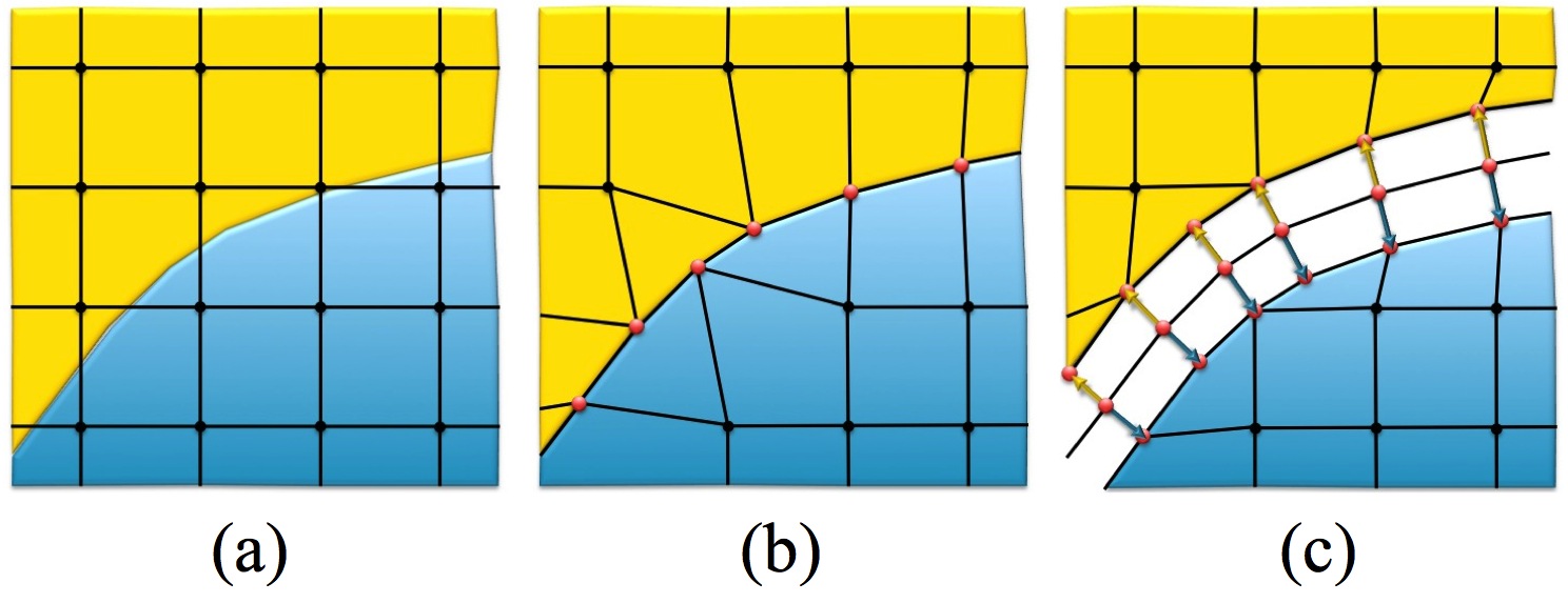
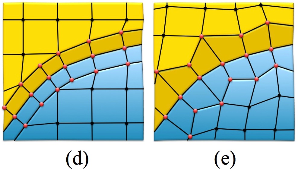
The basic Sculpt procedure is illustrated in figure 1. Beginning with a Cartesian grid as the base mesh, shown in figure 1(a), a geometric description is imposed. Nodes from the base grid that are near the boundaries are projected to the geometry, locally distorting the nearby hex cells (figure 1(b)). A pillow layer of hexes is then inserted at the surfaces by duplicating the interface nodes on either side of the boundaries and inserting hexes (figures 1(c) and (d)). While constraining node locations to remain on the interfaces, smoothing procedures can now be employed to improve mesh quality of nearby hexes (figure 1(e)).
Figure 1. The procedure for generating a hex mesh
using the Sculpt overlay grid method
Sculpt is limited to capturing geometric features with the available resolution of the selected base mesh. Because of this, care should be taken in selecting an appropriate cell size. In addition, no attempt is made by the Sculpt procedure to capture sharp exterior features. Figure 2 shows an example of a sculpt mesh of a CAD model. Note that exterior corner features are rounded, however the effect of sharp feature capture becomes less pronounced as resolution increases as demonstrated in figures 3(a) and (b).
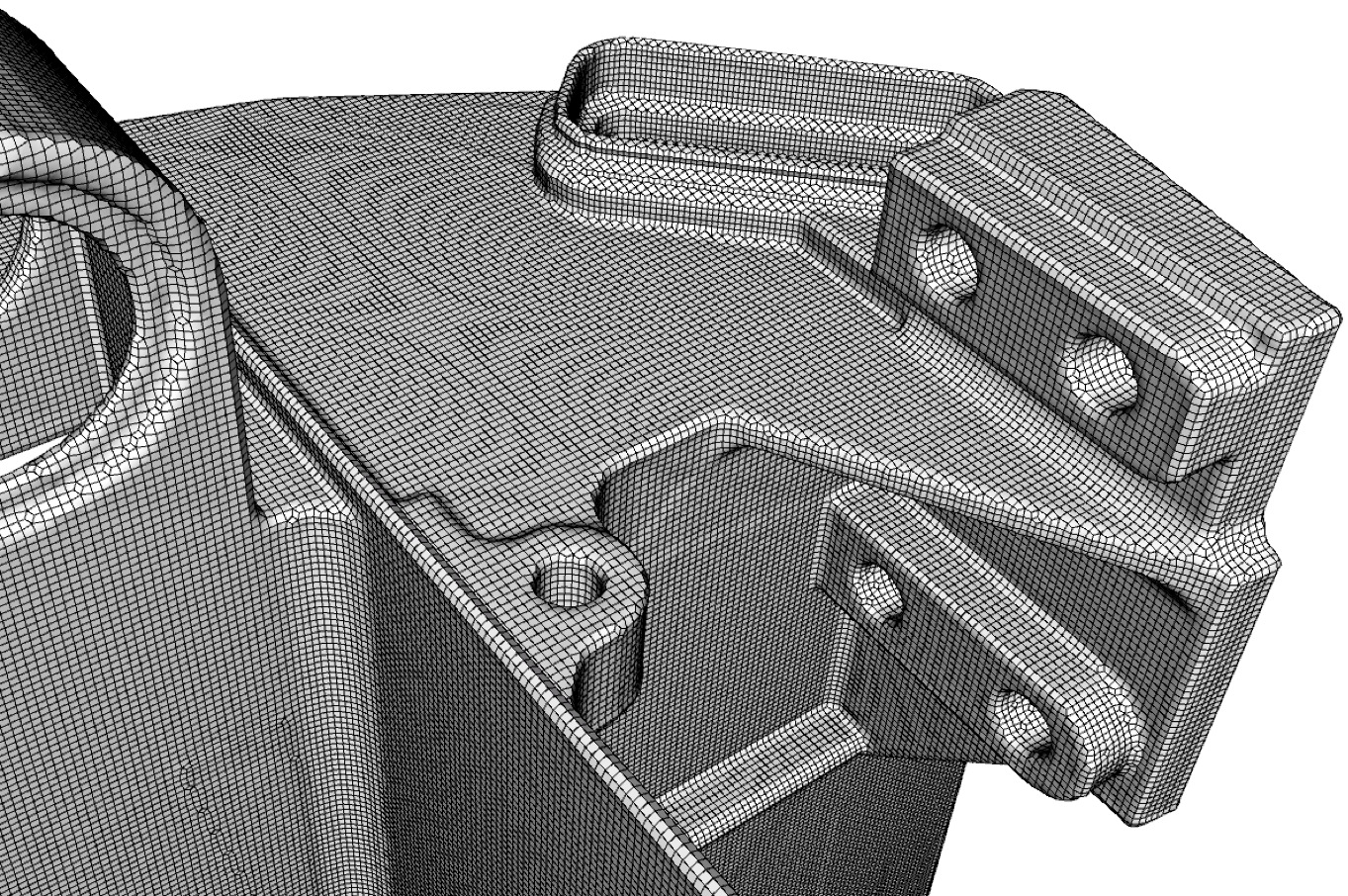 Figure 2. Hex mesh generated using the Sculpt
overlay grid procedure
Figure 2. Hex mesh generated using the Sculpt
overlay grid procedure 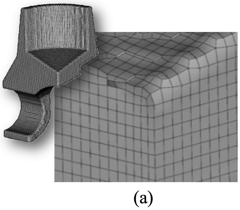
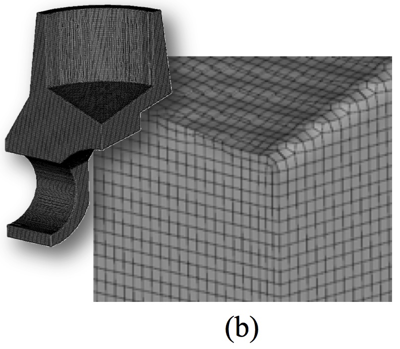 Figure 3. Examples
of the same model meshed at two different resolutions showing a cutaway
view of the mesh.
Figure 3. Examples
of the same model meshed at two different resolutions showing a cutaway
view of the mesh.
Another aspect of model preparation for computational simulation involves geometry cleanup and simplification. In most cases, geometry-first methods, such as Sweeping, require an accurate non-manifold boundary representation before mesh generation can begin. Small, sometimes unseen gaps, overlaps and misalignments can result in sliver elements or mesh failure. Tedious manual geometry simplification and manipulation is often required before meshing can commence. Sculpt, however employs a solution that avoids much of the geometry inaccuracy issues inherent in CAD design models. Using a faceted representation of the solid model, a voxel-based volume fraction representation is generated. Figure 4 illustrates the procedure where a CAD model serving as input (figure 4(a)) is processed by a procedure that will generate volume fraction scalar data for each cell of an overlay Cartesian grid (figure 4(b)). One value per material per cell is computed that represents the volume fraction of material filling the cell. A secondary geometry representation is then extracted using an interface tracking technique from which the final hex mesh is generated (figure 4(c)). While similar to its initial facet-based representation, the new secondary geometry description developed from the volume fraction data results in a simplified model that tends to wash over small features and inaccuracies that are smaller than the resolution of the base cell size.
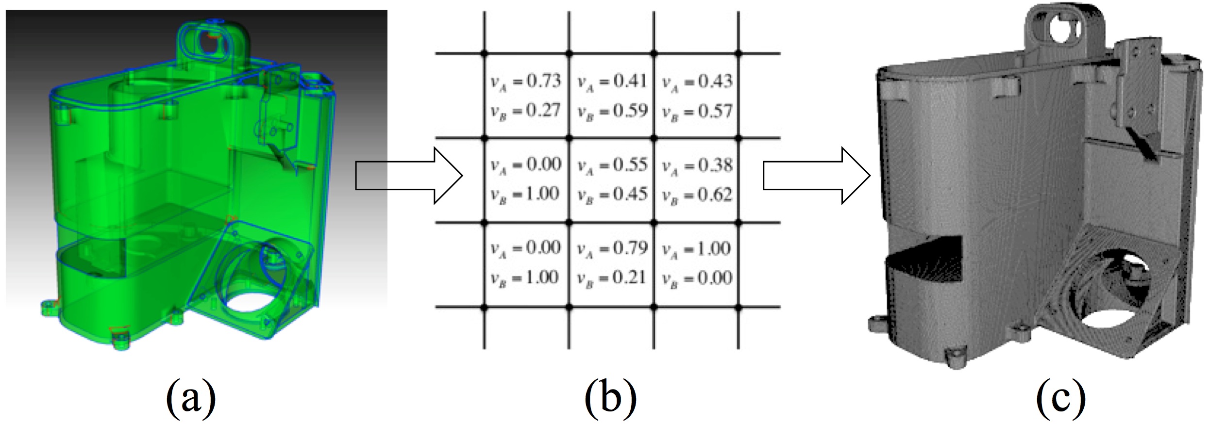
Figure 4. A representation of the procedure used to generate a hex mesh with Sculpt using Volume Fractions.
While acknowledging some loss in model fidelity in this new volume-fraction based geometric model, the advantage and time-savings to the analyst of being able to ignore troublesome geometry issues is enormous. At the same time it may be important to understand what the additional discrete approximations will make to solution accuracy and employ relevant engineering judgement in the use of this technology.
The following technical papers, written by the author of Sculpt, describe the Sculpt procedure in more depth. These papers were presented at the International Meshing Roundtable and are external links to pdf documents.
Parallel Hex Meshing from Volume Fractions: Describes the basic algorithms and mathematics used in the Sculpt procedure.
Parallel Smoothing for Grid-Based Methods: A brief description of the smoothing procedures used in Sculpt.
Validation of Grid-Based Hex Meshes with Computational Solid Mechanics: Describes a study where computational results from Sculpt meshes are compared with Sweep meshes using the Sierra Solid Mechanics Tool as a comparison.
A Template-Based Approach for Parallel Hexahedral Two-Refinement: Describes the refinement procedures used for generating adapted Sculpt meshes.