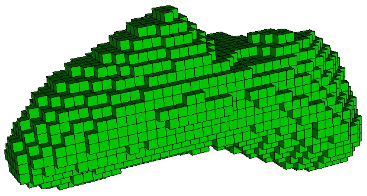
Example stair-step mesh on STL geometry.
Cubit 16.10 User Documentation
Sculpt options for specifying the type of mesh that will be generated. The default mesh type that will be produced from Sculpt is an unstructured all-hex mesh that will attempt to conform as closely as possible to the input geometry. Sculpt will normally generate its mesh on the interior of the input geometry, however with the mesh_void option, it can also generate the mesh on the exterior of the geometry, out to the extent of the user-defined Cartesian overlay grid.
In addition to the default hex mesh, other types of meshes may be produced. This includes the stair-step mesh where the cells of the Cartesian grid inside or intersecting the geometry are used directly as the mesh without projections or smoothing. A triangle mesh may also be generated, which can be used as the basis for a facet-based geometry representation. Other methods include the capabilities to generate a hex-dominant mesh with hexes and tets as well as the ability to include degenerate elements.
Mesh Type                    -typ     --type
  --stair                    -str  <arg> Generate Stair-step mesh
  --mesh_void                -V    <arg> Mesh void
  --trimesh                  -tri        Generate tri mesh of geometry surfaces
  --tetmesh                  -tet  <arg> Under Development
  --deg_threshold            -dg   <arg> Convert hexes below threshold to degenerates
  --max_deg_iters            -dgi  <arg> Maximum number of degenerate iterations
  --htet                     -ht   <arg> Convert hexes below quality threshold to tets
  --htet_method              -hti  <arg> Method used for splitting hexes to tets
  --htet_material            -htm  <arg> Convert hexes in given materials to tets
  --htet_transition          -htt  <arg> Transition method between hexes and tets
  --htet_pyramid             -htp  <arg> Local transition pyramid
  --htet_tied_contact        -htc  <arg> Local transition tied contact
  --htet_no_interface        -htn  <arg> Local transition none
  --periodic                 -per        Generate periodic mesh
  --check_periodic           -cp   <arg> Check for periodic geometry
  --check_periodic_tol       -cpt  <arg> Tolerance for checking periodicity
  --periodic_axis            -pax  <arg> Axis periodicity is about
  --periodic_nodesets        -pns  <arg> Nodesets ids of master/slave nodesets
Sculpt Command Summary
Command: stair     Generate Stair-step mesh
Input file command:   stair <arg>
Command line options: -str <arg>
Argument Type:        integer (0, 1, 2, 3)
Input arguments: none (0)
                 off (0)
                 on (1)
                 full (1)
                 interior (2)
                 fast (3)
Command Description:
Example stair-step mesh on STL geometry.
The stair option generates a stair-step mesh where the cells of the Cartesian grid are used in the final mesh without projection or smoothing to the material interfaces. Cells selected from the Cartesian grid to be used in the final mesh will have volume fraction greater than 0.5. Several different options for the stair argument are available:
off (0): Stair option is off (default)
full (1): Stair-step mesh is generated, but additional processing is done to ensure material interfaces are manifold. This option may add or subtract cells from the basic mesh (where volume fraction > 0.5) to ensure no non-manifold connections between nodes and edges exist in the final mesh.
interior (2): The exterior boundary will be smooth while internal material interfaces will be stair-step. This option also ensures manifold connections between elements.
fast (3): Generates the final mesh based only on volume fraction criteria. No additional processing is done to ensure manifold connections between edges and nodes.
Command: mesh_void     Mesh void
Input file command:   mesh_void <arg>
Command line options: -V <arg>
Argument Type:        true/false or only
Input arguments: off (0)
                 false (0)
                 on (1)
                 true (1)
                 only (2)
Command Description:
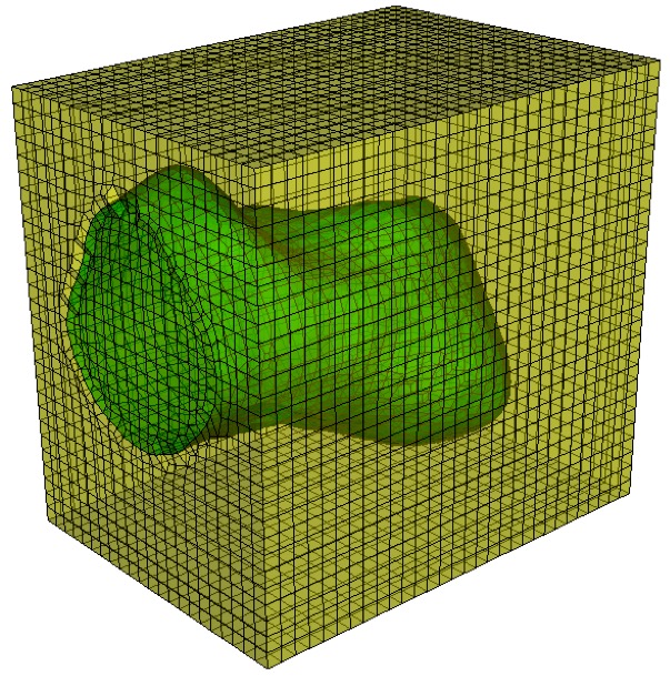
Mesh is generated in the void region surrounding the STL geometry.
The mesh_void accepts the following parameters:
off (0): No mesh is generated in the void region
on (1): Mesh is generated in the void region
only (2): Mesh is generated only in the void region and not in the material
If mesh_void option is set to on or only, then the void space surrounding the geometry will be treated as a separate material. Elements will be generated in the void to the extent of the Cartesian grid boundaries. If void_mat option is not used, the material ID of elements in the void region will be the maximum material ID in the model + 1. See also the separate_void_blocks option to separate the void elements into contiguous blocks.
Command: trimesh     Generate tri mesh of geometry surfaces
Input file command:   trimesh
Command line options: -tri
Command Description:
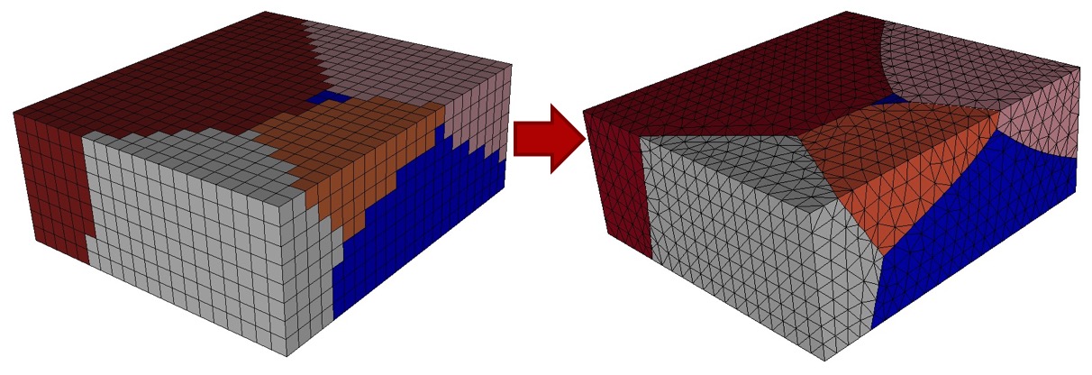
Trimesh generated from voxel microstructure data.
Generate a triangle mesh of the surface geometry. Surface geometry will be defined based on input grid resolution as well as user defined smoothing smoothing parameters. Resulting exodus mesh will contain only TRI elements. All TRI elements will be assigned to the same block in the exodus file.
This option is most often used in conjunction with the --write_geom option used to build a mesh-based geometry in Cubit. Use the following command in Cubit to import a Sculpt trimesh exodus file and s2g file (produced from --write_geom)
import s2g <root filename>
See write_geom for more information on s2g files.
Command: tetmesh     Under Development
Input file command:   tetmesh <arg>
Command line options: -tet <arg>
Argument Type:        none
Input arguments: off (0)
                 on (1)
                 true (1)
                 meshgems (2)
Command Description:
Under Development - uses space-filling tets as base grid. Size and extent is defined by bounding box options.
The meshgems (2) option uses a third party tet mesher to place interior tets. Triangle mesh is defined by splitting quads on surface. Both tetmesh options are currently only implemented for serial execution.
Command: deg_threshold     Convert hexes below threshold to degenerates
Input file command:   deg_threshold <arg>
Command line options: -dg <arg>
Argument Type:        floating point value (-1.0 -> 1.0)
Command Description:
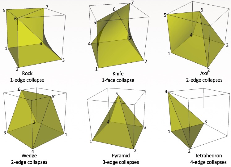
Examples of degenerates hexes where select edges have been collpased.
Some geometries will not permit a usable mesh with a traditional all-hex mesh. Sculpt includes the option to automatically and selectively collapse element edges to improve low-quality elements. The max_deg_iters and the deg_threshold values are used to control the creation of degenerates. Degenerate elements are treated as standard hex elements, but use repeated nodes in the eight-node connectivity array.
The deg_threshold value indicates scaled Jacobian threshold for edge collapses. Nodes at hexes below this threshold will be candidates for edge collapses, provided doing so will improve the minimum scaled Jacobian at the neighboring hexes. Default is -1.0.
Command: max_deg_iters     Maximum number of degenerate iterations
Input file command:   max_deg_iters <arg>
Command line options: -dgi <arg>
Argument Type:        integer >= 0
Command Description:
Maximum number of edge collapse iterations to perform to create degenerate hex elements. Default is 0. See also deg_threshold
Command: htet     Convert hexes below quality threshold to tets
Input file command:   htet <arg>
Command line options: -ht <arg>
Argument Type:        floating point value (-1.0 -> 1.0)
Command Description:
Tet elements generated where quality drops below threshold.
Automatically generate tets in place of poor quality elements. This option can be used to eliminate poor quality hex elements by replacing each hex that falls below the user defined Scaled Jacobian with 6 or 24 tets. The method used for splitting is controlled by the htet_method option. The default threshold value for htet is -1.0, which turns off the generation of all tets. A value of 1.0 will split all hexes into tets.
If a neighboring element is a hex, and will not be split, one may choose whether to use pyramid transitions or have hanging nodes. The default is to have hanging nodes with a tied contact condition being created. The transition type may be specified with the htet_transition command.
If tet blocks are created, their ids will be the material id plus an offset based on the maximum material id. Likewise, any pyramid blocks created will be offset as well, with their ids coming after hex block ids if there are no tets, or with their ids coming after tet blocks.
Command: htet_method     Method used for splitting hexes to tets
Input file command:   htet_method <arg>
Command line options: -hti <arg>
Argument Type:        integer (1, 2)
Input arguments: none (0)
                 structured (1)
                 unstructured (2)
Command Description:
Specifies which method is used for splitting hexes into tets:
structured (0): Each hex is subdivided into 24 tets. Additional nodes are The 24 tets are formed by inserting one node at the center of each face and one on the interior.
unstructured (1): Each hex is subdivided into 6 tets. No additional nodes are inserted. Note that the unstructured method does not currently support the htet_transition options pyramid and tied_contact.
Default htet_method is structured (0).
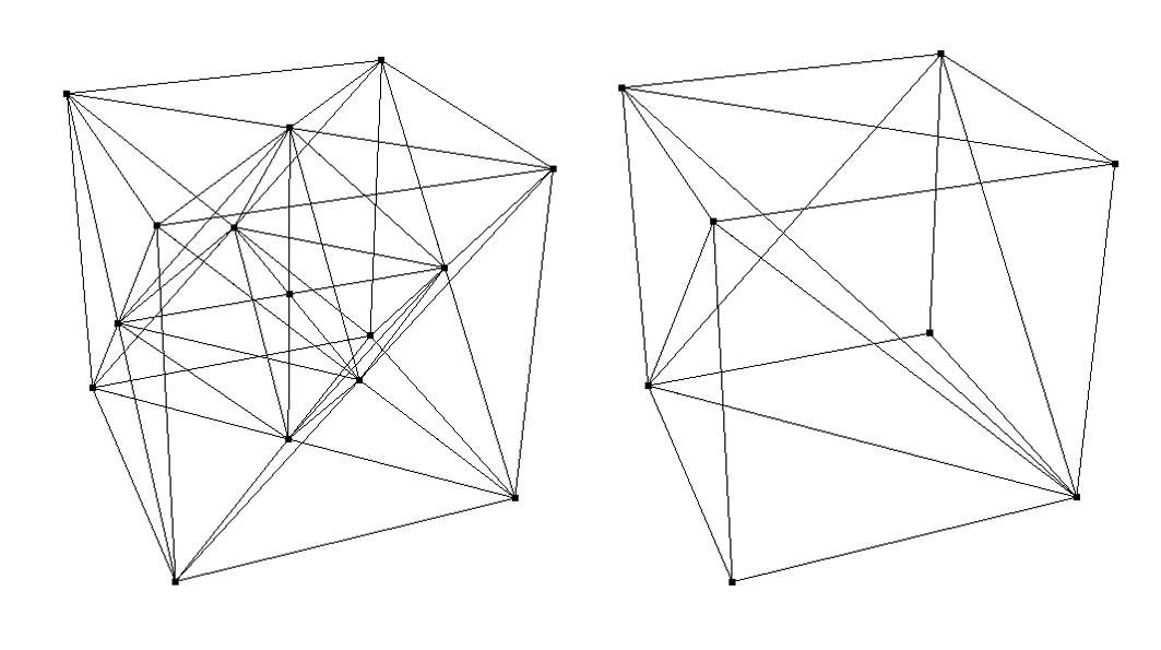
Left: Structured htet_method subdivides each hex into 24 tets. Right: Unstructured htet_method subdivides each hex into 6 tets
Command: htet_material     Convert hexes in given materials to tets
Input file command:   htet_material <arg>
Command line options: -htm <arg>
Argument Type:        integer >= 0
Command Description:
Generate tets in place hexes in a given material. This option can be given multiple times to specify multiple materials. Each hex in a material is replaced with 24 tets. The 24 tets are formed by inserting one node at the center of each face and one on the interior.
If an neighboring element is a hex, and will not be split, one may choose whether to use pyramid transitions or have hanging nodes. The default is to have hanging nodes with a tied contact condition being created. The transition type may be specified with the htet_transition command.
If tet blocks are created, their ids will be the material id plus an offset based on the maximum material id. Likewise, any pyramid blocks created will be offset as well, with their ids coming after hex block ids if there are no tets, or with their ids coming after tet blocks.
    htet_material = 10
    htet_material = 12
    htet_transition = pyramid
    htet_no_interface =  10 13
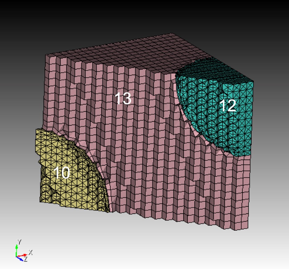
Simple example of the use of hybrid tet-hex capability using the above example input. Materials 10 and 12 use tet elements while 13 remains hexes. The default transition is to use pyramids, while the specific interface between 10 and 13 has no interface.
Command: htet_transition     Transition method between hexes and tets
Input file command:   htet_transition <arg>
Command line options: -htt <arg>
Argument Type:        none/pyramid/tied_contact
Input arguments: none (0)
                 pyramid (1)
                 tied_contact (2)
Command Description:
When generating tets adjacent to hexes, the transition type between the two elements can be defined. Possible options are:
If pyramid transition is specified, the hex may be split into 1 pyramids and 20 tets, 2 pyramids and 16 tets, 3 pyramids and 12 tets, and so forth. The mesh will remain conformal if pyramid transition is specified.
A tied contact condition can be defined to ensure continuity of the neighboring tets and hexes. To facilitate this, one additional nodeset and sideset will be generated and output to the exodus file if the gen_sidesets = variable (2) option is specified. The sideset and nodeset will be identified with the following IDs:
Sideset 10000 = the set of hex faces that interface a set of 4 tets.
Nodeset 1000 = the set of nodes at the interface between hexes and tets. One node per face in Sideset 10000 will be included.
Command: htet_pyramid     Local transition pyramid
Input file command:   htet_pyramid <arg>
Command line options: -htp <arg>
Argument Type:        integer(s) >= 0
Command Description:
When generating tets adjacent to hexes, pyramid transitions can be specified for a given material or material interface. To specify a material interface, two material ids are given to specify pyramid transition between the two materials. To specify multiple materials or multiple material interfaces, this command may be used multiple times.
Command: htet_tied_contact     Local transition tied contact
Input file command:   htet_tied_contact <arg>
Command line options: -htc <arg>
Argument Type:        integer(s) >= 0
Command Description:
When generating tets adjacent to hexes, tied contact transitions can be specified for a given material or material interface. To specify a material interface, two material ids are given to specify tied contact transition between the two materials. To specify multiple materials or multiple material interfaces, this command may be used multiple times.
Command: htet_no_interface     Local transition none
Input file command:   htet_no_interface <arg>
Command line options: -htn <arg>
Argument Type:        integer(s) >= 0
Command Description:
When generating tets adjacent to hexes, no transition can be specified for a given material or material interface. To specify a material interface, two material ids are given to specify no transition between the two materials. To specify multiple materials or multiple material interfaces, this command may be used multiple times.
Command: periodic     Generate periodic mesh
Input file command:   periodic
Command line options: -per
Command Description:
Generates a periodic mesh for either Cartesian or unstructured mesh input. Ensures that resulting mesh nodes and faces are precisely matching on opposite sides of the mesh.
Unstructured mesh input: When used with the --input_mesh option opposite sides of the mesh must be identified using pairs of leading and trailing nodesets using the --periodic_nodesets (-pns) option. Nodes in the nodeset pairs must be separated by a constant translation or rotation. If a rotation is used between leading and trailing nodesets, the --periodic_axis (-pax) option must be used. If not used, then the transformation is assumed to be pure translation. Input geometry is assumed to be periodic with a period equal to that of the input mesh. Results from non-periodic geometry used with the periodic option may be unpredictable. The following is an example of an input file that uses the periodic option on an unstructured input mesh:
   BEGIN SCULPT
      diatom_file = geometry_file.diatom
      input_mesh = input_exodus_file.g
      exodus_file = output_exodus_file
      smooth = to_geometry
      capture = 5
      capture_angle = 10
      free_surface_sideset = 1000
      gen_sidesets = input_mesh_and_free_surfaces
      periodic = true
      periodic_nodesets = 3224 3225
      periodic_axis = 0 0 0 0 1 0
   END SCULPT
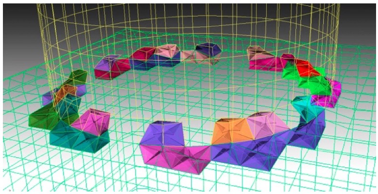
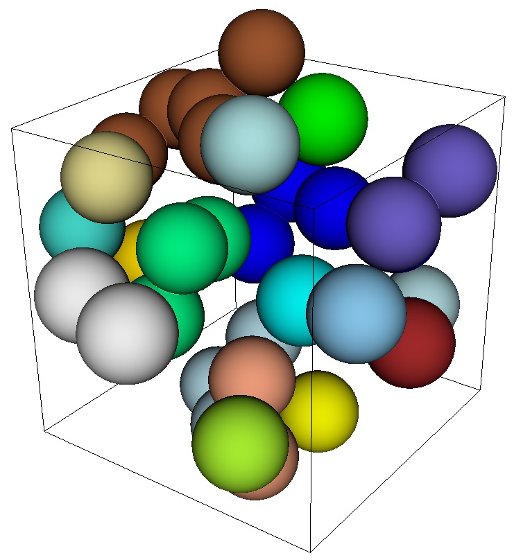
Cartesian grid input: This option is often used for computational materials modeling. Sculpt can generate a true periodic mesh in a representative volume element (RVE) where meshes on all opposite faces of the RVE will precisely match. When used with a Cartesian grid, the --periodic_nodesets and --periodic_axis options are ignored. The following is an example sculpt input file that utilizes the --periodic option on a Cartesian grid with geometry defined in a diatom file. It also utilizes the --adapt_type option to automatically refine and the gen_sidesets = RVE option to generate sidesets at the six RVE faces.
   BEGIN SCULPT
      diatom_file = spheres_periodic.diatom
      xmin = -18.705510
      ymin = -18.705510
      zmin = -18.705510
      xmax = 18.705510
      ymax = 18.705510
      zmax = 18.705510
      nelx = 38
      nely = 38
      nelz = 38
      periodic = true
      defeature = 1
      min_vol_cells = 10
      adapt_type = vfrac_average
      adapt_levels = 2
      adapt_threshold = 0.00001
      gen_sidesets = RVE
      exodus_file = spheres_periodic
      mesh_void = true
   END SCULPT
Geometry Requirements: In order to generate a valid periodic mesh, the input geometry must also be periodic and the bounding box parameters should span exactly one period of the geometry. To check the periodicity of the geometry and prescribed bounding box, see the check_periodic option.
Note: The resulting mesh at the boundaries of the Cartesian grid (RVE) will not be projected to the planes of the bounding box. The result will be a "ragged" boundary in order to maintain periodicity between nodes on opposite sides of the mesh. Also note that results from the use of the periodic option may be undefined or unstable when used with non-periodic input geometry.
Periodic geometry used for example described in diatom file. RVE boundary shown with respect to the geometry.
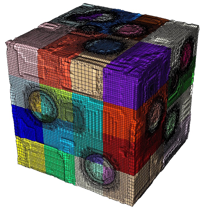
Resulting periodic mesh generated from example input.
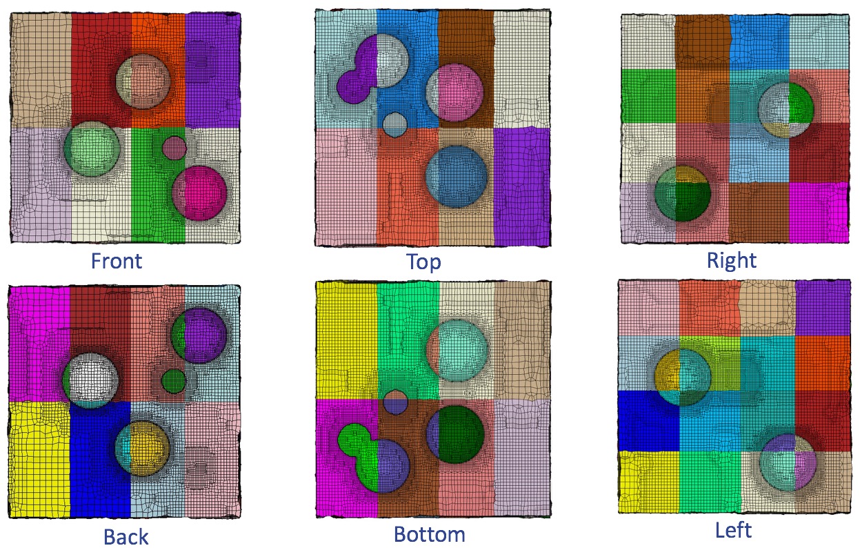
Six faces of the RVE from above example illustrating periodicity on a 32 processor decomposition. Note that top three images are a mirror image of the bottom three images.
Command: check_periodic     Check for periodic geometry
Input file command:   check_periodic <arg>
Command line options: -cp <arg>
Argument Type:        on, off, only
Input arguments: off (0)
                 on (1)
                 only (2)
Command Description:
When using the periodic option with a Cartesian base grid, the input geometry must be periodic with respect to the grid bounding box in order to meet the minimum requirements of a valid periodic mesh. The bounding box must span exactly one period in each dimension. If this requirement is not met, a valid mesh may still be generated, however, periodicity will not be guaranteed. The check_periodic option is used to check this requirement. See also check_periodic_tol to set the tolerance for checking periodicity.
Options:
The check_periodic option is ignored if the periodic option is OFF or set to false.
Command: check_periodic_tol     Tolerance for checking periodicity
Input file command:   check_periodic_tol <arg>
Command line options: -cpt <arg>
Argument Type:        floating point value
Command Description:
Used on conjunction with the check_periodic option. It specifies a tolerance value when checking periodicity. Check periodic option checks the difference between computed volume fractions for cells on the overlay grid that are separated by exactly one period. The periodic tolerance is the allowable volume fraction difference between cells separated by one period. Default value is 1e-6.
Command: periodic_axis     Axis periodicity is about
Input file command:   periodic_axis <arg>
Command line options: -pax <arg>
Argument Type:        six floating point values
Command Description:
For an unstructured base grid, specifies an axis about which the nodes in the master (leading) nodesets will be rotated about to produce the slave (trailing) nodesets. Six floating point numbers are specified, the first three define the origin of the axis and the last three define the axis direction. This option must be used with --periodic (-per), --periodic_nodesets (-pns), and --input_mesh (-im) options. If the --periodic (-per) option is used without the --periodic_axis option, the transformation between leading and trailing nodesets is assumed to be pure translation.
Command: periodic_nodesets     Nodesets ids of master/slave nodesets
Input file command:   periodic_nodesets <arg>
Command line options: -pns <arg>
Argument Type:        integer(s) >= 0
Command Description:
For an unstructured base grid, specifies the master-slave (leading-trailing) nodeset pairs. Master nodesets should be able to be translated or rotated about a specified axis to produce the nodes in the slave nodesets. Nodesets must be specified in pairs, where each master (leading) nodeset corresponds to a single slave (trailing) nodeset. Each nodeset pair must maintain an identical translation or rotation. If a rotation is used, the axis and origin of rotation must be specified with the --periodic_axis (-pax) option. This option should be used with --periodic (-per), --periodic_nodesets (-pns), and --input_mesh (-im) options.)
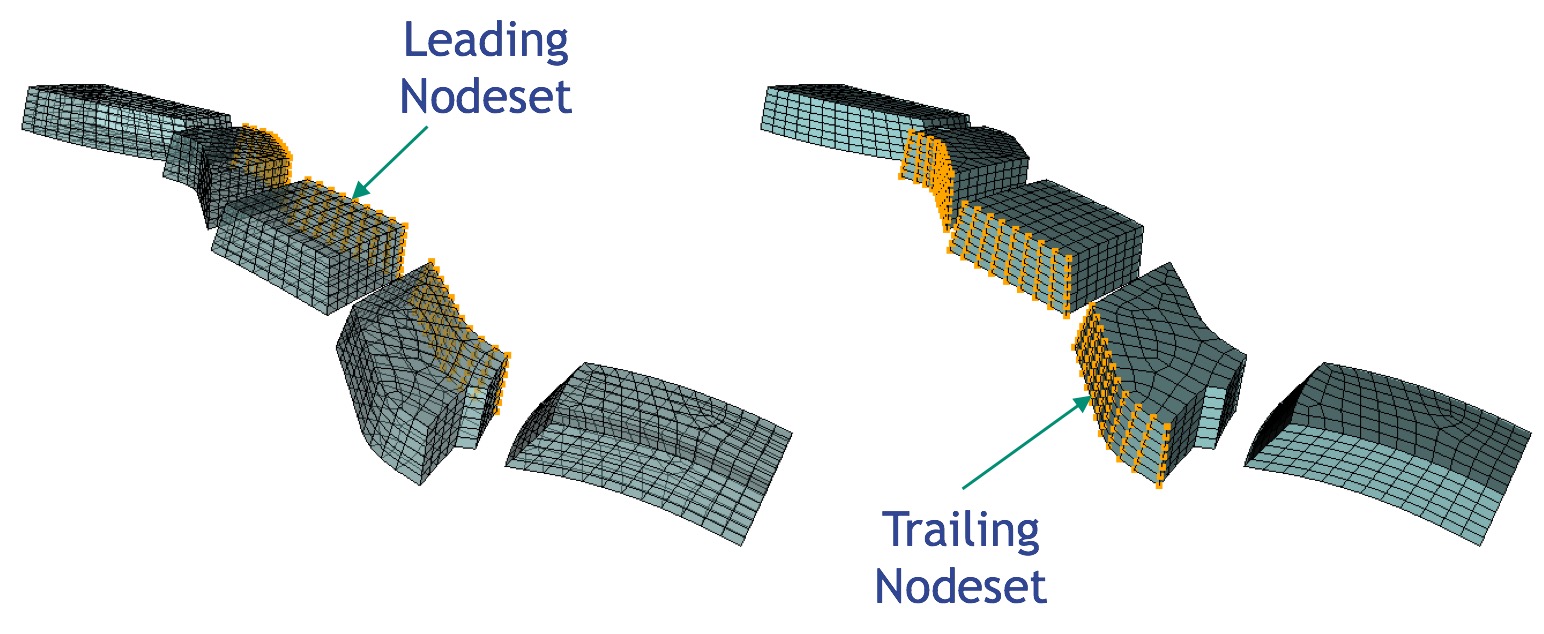
Unstructured input mesh used to generate periodic mesh. Matching leading and trailing nodesets are defined in the exodus file.