Cubit 16.04 User Documentation
Applies to: Surfaces
Summary: Automatically meshes surface geometry with triangle elements using the third part meshgems tool.
Syntax:
Surface <range> Scheme TriMesh [Geometry Approximation Angle <angle>] [Meshgems] [Minimum Size <value>]
Related Commands:
[Set] Trimesher Minimum Size <value>
[Set] Trimesher Surface Gradation <value>
[Set] Trimesher Volume Gradation <value>
[Set] Trimesher Geometry Sizing {ON|off}
[Set] Trimesher Clean Discrete {on|OFF}
[Set] Trimesher Discrete Composites {on|OFF}
[Set] Trimesher Split Overconstrained Edges {on|OFF}
[Set] Trimesher Ridge Angle {<value=100>}
[Set] Trimesher Anisotropic layers {on|OFF [<layers=2>]}
Discussion:
The TriMesh scheme fills a surface of arbitrary shape with triangle elements. The TriMesh scheme serves as the default method for meshing the surfaces of volumes for the TetMesh scheme.
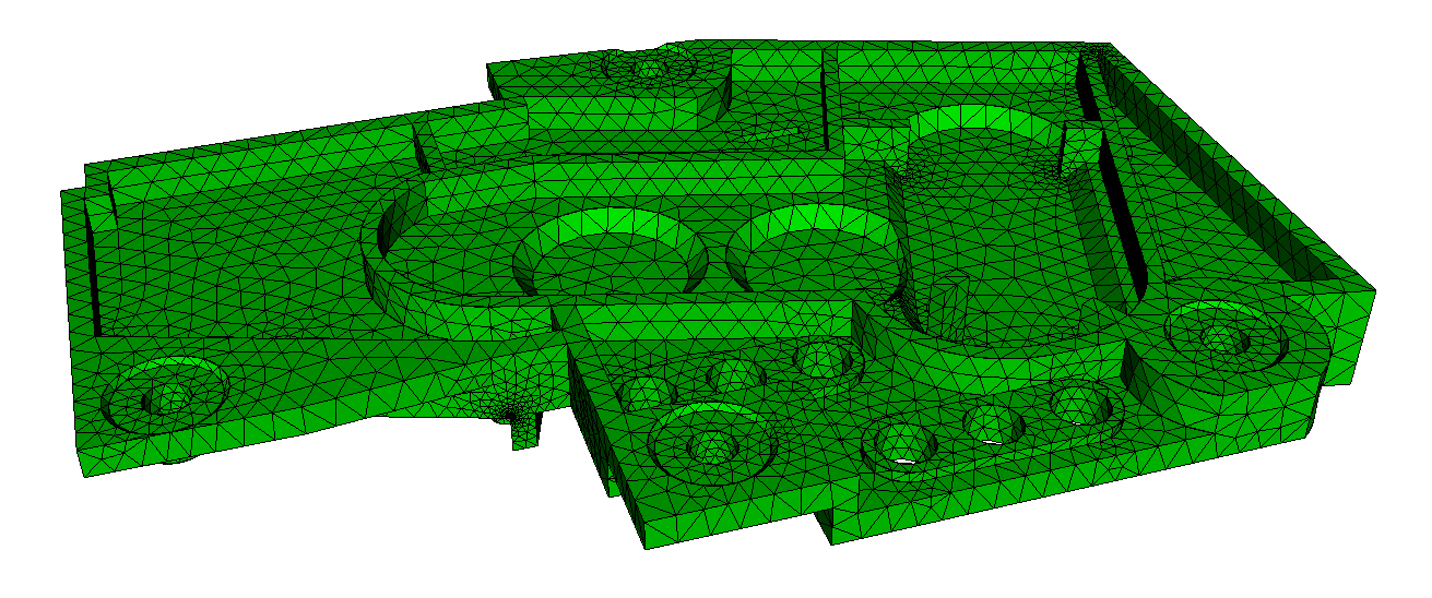
Included in Cubit is a third party software library for generating triangle meshes called MeshGems. This is a robust and fast triangle mesher developed and distributed by Distene. Figure 1 shows a CAD model where surfaces have been meshed with the TriMesh scheme. The triangle mesh was then used as input to the TetMesh scheme.
Figure 1. Triangle meshes generated with the TriMesh scheme using default settings on the surfaces of a CAD model.
The TriMesh scheme is usually very good at generating a mesh with its default settings. In most cases no adjustments to default settings are necessry. Using the size assigned to the surface, either assigned explicitly or defined with an auto size, the TriMesh scheme will attempt to maintain the assigned size, except where features smaller than the specified size exist. In this case, smaller triangles will automatically be generated to match the feature size. The triangle mesher will then generate a smooth gradation from the small triangles used to capture features, to the size specified on the surface. This effect is shown in figure 1 where the transitions in triangle sizes can be seen. If no size is specified on the surface, it will use the size that was set on its parent volume. User defined sizes and intervals can also be assigned to individual curves for more specific control of element sizes.
Although rare, if meshing fails when using the TriMesh scheme, Cubit will automatically attempt to mesh the surface with the TriDelaunay scheme. Subsequent mesh failures will also attempt meshing with the TriAdvance and QTri schemes.
A sizing function can also be used with the TriMesh scheme to control element sizes, however the algorithm used for meshing will automatically revert to the TriAdvance scheme. This is because the MeshGems algorithm provides built-in capabilities for adaptively controlling the element sizes based on geometry. More details can be found in Geometry Adaptive Sizing for TriMesh and TetMesh Schemes
When using the TriMesh and TetMesh schemes, recommended practice is to mesh all surfaces and volumes simultaneously. This provides the greatest flexibility to the algorithms to determine feature sizes and their effect on neighboring surfaces and volumes.
The TriMesh options described below can be set to adjust the default behavior of the tri mesher. Scheme options are assigned independently to each surface as part of the scheme TriMesh command. Note that the options described here will apply only if the TriMesh scheme is used. TriDelaunay and TriAdvance schemes will not utilize these options when meshing.
Geometry Approximation Angle <angle>
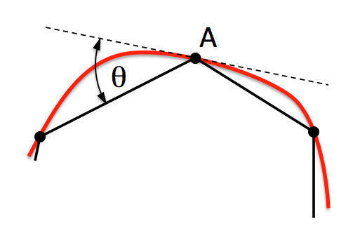
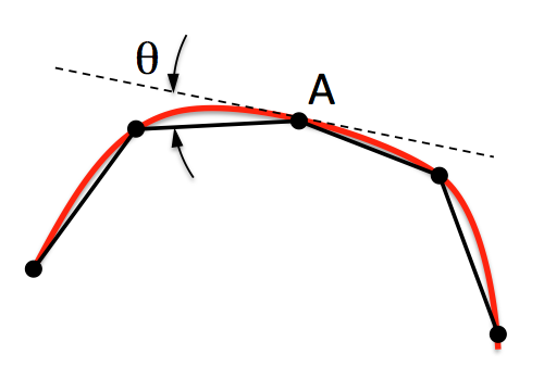
For non-planar CAD surfaces and non-linear curves, an approximation must always be made to capture the curved features using the linear edges of the triangle. When a geometry approximation angle is specified, the triangle mesher will adjust triangle sizes on curved boundaries so that the linear edges of the triangle will deviate from the geometry by no greater than the specified angle. Figure 2 illustrates how the geometry approximation angle is determined. If the red curve representes the geometry and the black segments represent the mesh, the angle θ is the angle between the tangent plane at point A and the plane of a triangle at A. θ represents the maximum deviation from the geometry that the mesh will attempt to capture. As shown in figure 2(b), a smaller geometry approximation angle will normally result in more elements, but it will more closely approximate the actual geometry. The default approximation angle is 15 degrees.
 |
 |
(a) |
(b) |
Figure 2. The geometry approximation angle θ is shown as the maximum deviation between the tangent plane at A and the plane of a triangle at A.
Note that the geometry approximation angle is also effective in controlling the element size on the interior of surfaces as illustrated in figure 3. This is most useful when used in conjunction with the TetMesh Scheme where smaller tets will be placed in regions of higher curvature.
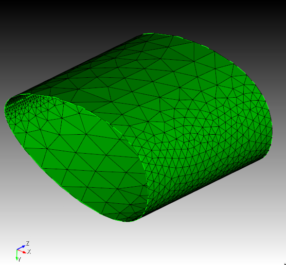
Figure 3. Demonstrates the effect of the geometry approximation angle to better capture surface curvature on the interior of surfaces.
Minimum Size <value>
By specifying a minimum size, the tri mesher will attempt to prevent creating elements smaller than this specified size. It should be noted that there may still be a small number of elements with a size slighly less that this value; it is not an exact setting.
The MeshGems option will use only the MeshGems triangle mesher on the specified surfaces. It will not revert upon failure to the TriDelaunay or TriAdvance schemes.
The user may set options that control the gradation of the tri-meshing algorithms. These trimesher options are global settings and apply to all trimeshes generated when the scheme is set to TriMesh until the option is changed by the user.
The minimum size setting controls the smallest edge length generated during triangle meshing.
[Set] Trimesher Minimum Size <value>
The global gradation options control how fast the triangle sizes can change when transitioning from small to larger sizes. For example a value of 1.5 will attempt to limit the change in element size of adjacent triangles to no greater than a factor of 1.5. Valid values for gradation should be greater than 1.0 and usually less than 2 or 3. The larger the value, the faster the transition resulting in fewer total elements. Likewise, values closer to 1.0 can result in significantly more elements, especially when small features are present. The default setting for gradation is 1.3. Gradation can be controlled for both surfaces and volumes.
[Set] Trimesher Surface Gradation <value>
Surface gradation will control the growth of triangles where element size has been determined by bounding curves. For example, Figure 4 shows a small feature where element sizes have been determined locally by the length of the small curves. A gradation is applied so that triangle sizes increase away from the small feature. A surface gradation of 1.3 is shown on the left, while a surface gradation of 1.1 is shown on the right.
 |
 |
(a) |
(b) |
Figure 4. Demonstrates the effect of changing the default gradation, where (a) is the default gradtion of 1.3, compared with (b) using a gradation of 1.1. Note that both images use the same interval size setting for the surface.
[Set] Trimesher Volume Gradation <value>
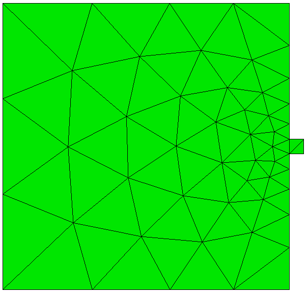
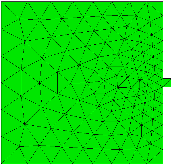
Volume gradation will control the growth of triangles where element size has been determined by the proximity of other nearby surfaces. For example, Figure 5a and 5b shows a brick with a small void where the surface meshes are generated with the TriMesh scheme. The surface gradation has been adjusted to a large number so its effect is negligible. The small element size determined for the void is propagated to the exterior surfaces. The resulting gradation of the nearby triangles on the surface is determined by the trimesh volume gradation setting.
Note that the trimesh volume gradation command is different than the growth factor control setting. The trimesh volume gradation controls the gradation of triangles on the surface due to nearby features where small tets will exist, whereas the volume <range> tetmesh growth_factor command controls the gradation of the interior tet elements.
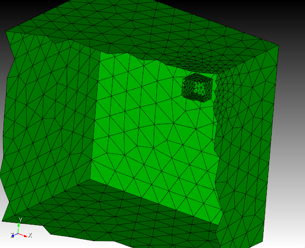
Figure 5a. An example of a cut-away mesh with a volume gradation, where the small size on the interior void propagates to the exterior surfaces
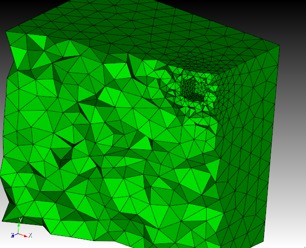
Figure 5a. An example of a cut-away mesh with a volume gradation, where the small size on the interior void propagates to the exterior surfaces
[Set] Trimesher Geometry Sizing {ON|off}
The global Geometry Sizing setting can be toggled on or off. If set to on, the element size will be influenced by the geometry approximation angle. If set to off, geometry approximation angle will not be involved in the computation of element size. See geometry approximtion angle for more information.
[Set] Trimesher Discrete Composites {on|OFF}
The option Discrete Composites forces trimeshing to convert the composite into a discrete (faceted) representation, from which the trimesher generates a mesh. The default behavior is to use the underlying geometry, if the composite has it, to generate a mesh. Using the underlying geometry is typically a more robust and reliable approach, not dependent on good faceting. However, it should be noted that composites with mesh curves will be triangle meshed with the discrete method, as this is not supported with the default method at this time but shortly will be.
[Set] Trimesher Clean Discrete {on|OFF}
The option Clean Discrete performs a step to 'clean' the faceting given to the trimesher for discrete surfaces (mesh-based geometry and composites), previous to triangle meshing. The 'cleaning' is actually a meshing of the facets which typically generate a better, more optimal set of facets representing the surface. This 'clean' step uses geometry approximation, with angle of 8 degrees to generate the new facets. The option is OFF by default.
[Set] Trimesher Ridge Angle {<value=100>}
The ridge_angle setting is only used when meshing discrete surfaces (composites or facet/mesh-based geometry surfaces). It is the threshold for deteremining when to preserve lines (ridges) defined in the discrete surface. Lines in the discrete surface having a dihedral angle larger than ridge_angle will be preserved in the generated triangle mesh. In Figure 7, the composite surface has a dihedral angle of 17° at its ridge. In the first image ridge_angle is set to less than 17° so the ridge is preserved. In the second image ridge_angle is set to greater than 17° so the ridge is not preserved.
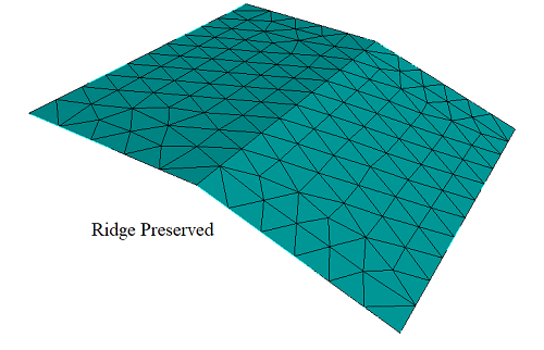

Figure 6. Ridge Angle Setting
[Set] Trimesher Split Overconstrained Edges {on|OFF}
The global Split Overconstrained Edges, if set to on, splits edges owned by the surface, but with both nodes on curves. This feature can help when two elements through the thickness of the mesh is desired. Figure 7 shows the effect of this option.
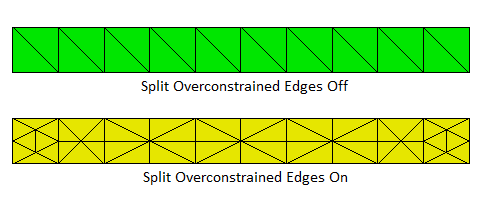
Figure 7. Split overconstrained edges
[Set] Trimesher Anisotropic Layers {on|OFF [<layers=2>]}
The Anisotropic Layers setting attempts to place the specified number of layers triangle through thin regions of the surface while respecting the surface mesh size in the thick direction. The default number of layers is two. This option is currently under development and can sometimes generate ill-formed triangles. The number of layers generated can sometimes exceed the number of layers specified..
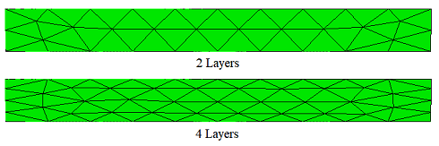
Figure 8. Anisotropic Surface Meshing