
Figure 1 Chamfer with two different distances
Cubit 16.04 User Documentation
The following options of the Tweak Curve command are available. Command syntax and description follow below.
The Tweak Curve Chamfer or Fillet command is used to fillet or chamfer a curve. The radius value is the radius of the fillet arc or chamfer cut distance. The command syntax is:
Tweak Curve <id_range> {Fillet|Chamfer} Radius <value> [Keep] [Preview]
In addition to creating chamfers of a single cut distance, the chamfer can be specified be two values. The syntax is:
Tweak Curve <id_list> Chamfer Radius <val1> [<val2>] [Keep] [Preview]
Figure 1 shows a brick ('br x 10') chamfered with two different cut distances ('Tweak Curve 1 2 Chamfer Radius 2 4').
Figure 1 Chamfer with two different distances
Individual curves can also be filleted with different start and finish radius values. The syntax is:
Tweak Curve <id> Fillet Radius <val1> [<val2>] [Keep] [Preview]
Figure 2 shows a brick ('br x 10') filleted with different start and end radius values (‘Tweak Curve 1 2 Chamfer Radius 2 4’).
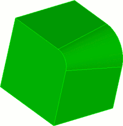
Figure 2. Fillet with two different radii
For all Tweak Fillet and Tweak Chamfer variations, the keep option prevents the destruction of the original geometry after the operation and the preview option temporarily displays the new geometry configuration without actually changing the geometry.
Tweak Curve <id_list> Offset <val> [Curve <id_list> Offset <val>] [Curve <id_list> Offset <val> ...] [Keep] [Preview]
Tweaking curves a specified distance offsets the existing curves and extends the attached surfaces to meet them. A positive offset value will enlarge the surface while a negative value will decrease the area of the attached surface. Different offset values can be specified for each curve. The keep option prevents the destruction of the original geometry after the operation. The preview option temporarily displays the new geometry configuration without actually changing the geometry. Figure 3 shows an example of offsetting a curve a specified distance.
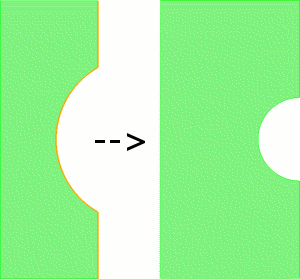
Figure 3 Offsetting a set of curves a specified distance
Tweak Curve <id_list> Remove [Keep] [Preview]
Similar to the Tweak Curve Remove command, the tweak curve remove function removes a specified curve from a sheet body. Figure 4 shows a simple example of removing a curve from a sheet body.
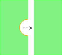
Figure 4. Removing a curve from a sheet body
The keep option prevents the destruction of the original geometry after the operation. The preview option temporarily displays the new geometry configuration without actually changing the geometry.
Use Tweak Curve Target to offset a curve to a specified surface, plane or curve. Figure 5 shows an example of tweaking a curve to several surfaces.
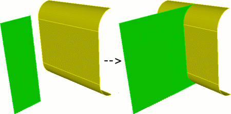
Figure 5 Tweaking a curve to multiple target surfaces
Similarly, a target plane can be specified using the Plane specification syntax. The Tweak Curve syntax is:
Tweak Curve <id_list> Target {Surface >id_list> [Limit Plane (options)] [EXTEND|Noextend] | Plane (options)} [Max_area_increase <val>] [Keep] [Preview]
Tweak Curve <id_list> Target Curve <id_list > [EXTEND|Noextend] [Max_area_increase <val>] [Keep] [Preview]
If a target surface is supplied, the user can also use a limit plane if he wishes. A limit plane is a plane that the tweak will stop at if the tweaked curve does not completely intersect the target surface. The limit plane must be used with the extend option. See the help for Specifying a Plane for the options available to define a plane.
It should be noted that if the source and target surfaces are from the same body the resulting geometry will be automatically stitched. Single target surfaces are automatically extended so that the tweaked body will fully intersect the target. Unfortunately, extending multiple target surfaces can sometimes result in an invalid target, so the option is given to tweak to non-extended targets with the noextend option. In this case, the tweaked body must fully intersect the existing targets for success. If you experience a failure when tweaking to multiple targets or the results are unexpected, it is recommended to try the noextend option (NOTE: Tweaking to multiple targets is only implemented in the ACIS geometry engine). If a value for the max_area_increasekeyword is given, Cubit will not perform the tweak if the resulting surface area increases by more than the specified amount. The keyword expects a percentage to be entered (i.e. '50' for 50%). It is recommended to always preview before using the tweak target commands.
For all tweak target variations, the keep option prevents the destruction of the original geometry after the operation and the preview option temporarily displays the new geometry configuration without actually changing the geometry.
Although it may not be intuitive curves can also serve as the target geometry. Figure 6 shows an example of extending a curve to another curve.
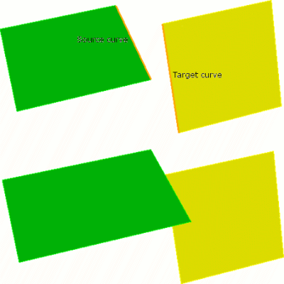
Figure 6 Tweaking a curve to a target curve
Notice that the source curve actually extends to the target curve as if the target were a surface.
When creating mid-surface geometry it is often useful to extend surfaces to form a corner. To handle this specific but common case use the tweak corner command.
Tweak Curve <id> <id> Corner [Preview]
Figure 7 shows a typical tweak corner example. Notice that surfaces are extended/trimmed to intersect at a corner.
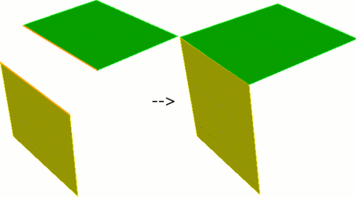
Figure 7. Tweaking two curves to a corner
The preview option temporarily displays the new geometry configuration without actually changing the geometry.