
Cubit 16.04 User Documentation

Note: This feature is under development. The command to enable or disable features under development is:
Set Developer Commands {On|OFF}
Grafting is used to merge a meshed surface with a dissimilar unmeshed surface. In the process, the location of the nodes on the meshed surface will be adjusted to fit to the bounding curves of the unmeshed surface and the connectivity of the original mesh may be changed to improve the final quality of the mesh. This allows an unmeshed volume to be attached--or grafted--onto a meshed volume. Grafting is particularly useful for models that have intersecting sweep directions (see example below).
The command syntax for grafting is:
Graft {Surface <range> | Volume <id>} onto Volume <id> [no_refine] [no_smooth]
The Graft command will check that the second volume is meshed. It then searches for surfaces on the second volume that overlap with the other volume or range of surfaces that is specified. If overlapping surfaces are found the mesh will then be adjusted on the second volume and after any needed imprinting is done the overlapping surfaces will be merged together.
[no_refine]: This option tells grafting not to modify the connectivity of the original mesh. The mesh is still adjusted to fit the boundary of the branch surface but no new elements are added.
[no_smooth]: This option tells grafting not to perform the final smoothing of the modified surface or volume mesh.
The following is a list describing the current scope and limitations of grafting:
Grafting Example
This example shows the four basic steps of grafting:
Step 1: Partition the geometry
Figure 1 shows the model that will be meshed. The arrows in the figure show the two intersecting sweep directions. Figure 2 shows the model decomposed for grafting.
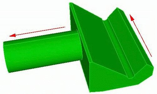
Figure 1. A model with two intersecting sweep directions.
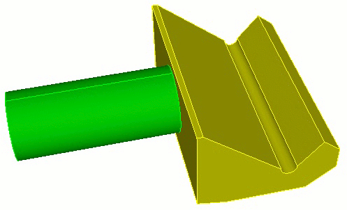
Figure 2. The model decomposed for grafting
Step 2: Mesh the trunk volume.
Figure 3 shows the mesh of the trunk volume. At this point the mesh on the trunk surface adjacent to the branch surface is a structured mesh that does not align with the boundary of the branch surface. The trunk and branch surfaces are two separate surfaces.
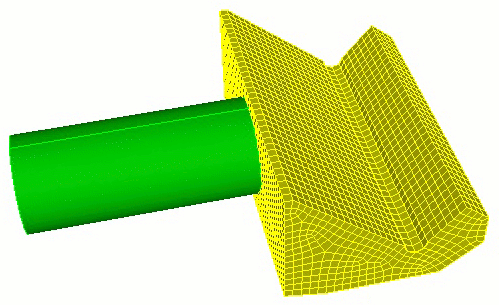
Figure 3. Meshed trunk volume.
Step 3: Graft the branch onto the trunk
Figure 4 shows the trunk surface after it has been modified to fit the branch surface. At this point the two surfaces have been merged together.
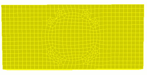
Figure 4. Trunk surface after grafting.
Step 4: Mesh the branch volume.
The final mesh is shown in Figure 5.
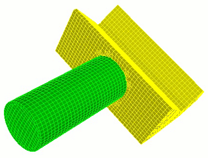
Figure 5. Final mesh