(a)
(b)
(c)
(d)
Cubit 15.4 User Documentation
Applies to: Volumes
Summary: Automatically meshes a volume with an unstructured tetrahedral mesh.
Syntax:
Volume <range> Scheme TetMesh [Proximity Layers {on[<num_layers>]|OFF}] [Geometry Approximation Angle <angle>]
Related Commands:
[Set] Tetmesher Add mid_edge_nodes {on|OFF}
[Set] Tetmesher Optimize Surface mid_edge_nodes {on|OFF}
[Set] Tetmesher Anisotropic layers {on|OFF [<layers=2>]}
[Set] Tetmesher Boundary Recovery {on|OFF}
[Set] Tetmesher HPC {ON|off} [Threads <value=4>]
[Set] Tetmesher HPC minimum size [<size>]
[Set] Tetmesher Interior Points {ON|off}
[Set] Tetmesher Optimize { { [Level <level> [Overconstrained Edges {on|OFF}] [Overconstrained Tetrahedra {on|OFF}] [Sliver {on|OFF}] } | Default }
[Set] Trimesher Surface Gradation <value>
[Set] Trimesher Volume Gradation <value>
[Set] Trimesher Geometry Sizing {ON|off}
[Set] Trimesher Split Overconstrained Edges {on|OFF}
THex Volume All
Volume <volume_id> Tetmesh Respect {Face|Tri|Edge|Node} <range>
Volume <volume_id> Tetmesh Respect Clear
Volume <volume_id> Tetmesh Respect File '<filename>'
Volume <volume_id> Tetmesh Respect Location (options)
Tetmesh Tri <range> [Make {Block|Group} [<id>]]
Tetmesh Tri <range> {Add|Replace} {Block|Group} <id>
Volume <id_range> Tetmesh growth_factor <value 1.0 to 10.0 = 1.05>
The TetMesh scheme fills an arbitrary three-dimensional volume with tetrahedral elements. The surfaces are first triangulated with one of the triangle schemes (TriMesh, TriAdvance or TriDelaunay) or a quadrilateral scheme with the quadrilaterals being split into two triangles (QTri). If a meshing scheme has not been applied to the surfaces, the TriMesh scheme will be used.
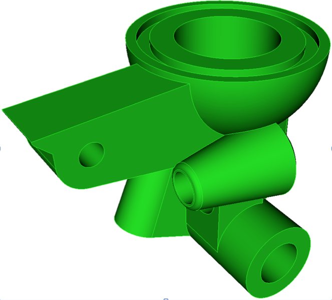
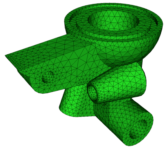
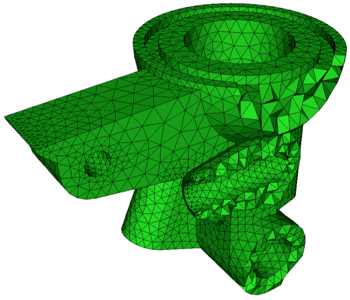
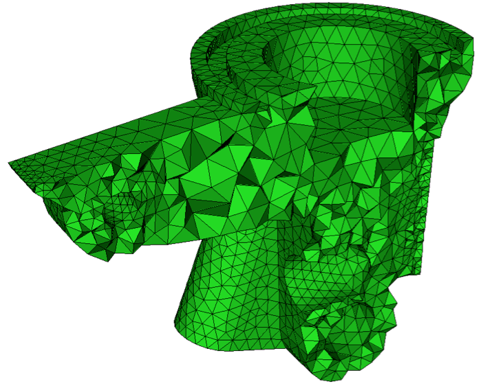
Included in Cubit is a third party software library for generating tetrahedral meshes called MeshGems. This is a robust and fast tetrahedral mesher developed by the French laboratory INRIA and distributed by Distene. It utilizes an algorithm for automatic mesh generation based upon the Voronoi-Delaunay method. Figure 1 shows a CAD model meshed with the TetMesh scheme, with the TriMesh scheme used to mesh the surfaces.
|
|
(a) |
(b) |
|
|
(c) |
(d) |
Figure 1. Tetrahedral mesh generated with the TetMesh scheme using default settings. (a) Initial CAD geometry (b) CAD model with surface mesh generated with TriMesh scheme. (c) and (d) Cut-away views of the interior tetrahedral mesh
The TetMesh scheme is usually very good at generating a mesh with its default settings. In most cases no adjustments to default settings are necessary. Using the size assigned to the volume, either assigned explicitly or defined with an auto size, the TetMesh scheme will attempt to maintain the assigned size, except where features smaller than the specified size exist. In this case, smaller tets will automatically be generated to match the feature size. The tet mesher will then generate a smooth gradation from the small tets used to capture features, to the size specified on the volume. This effect is shown in figure 1 where internal transitions in tetrahedra size can be seen. User defined sizes and intervals can also be assigned to individual surfaces and curves for more specific control of element sizes.
A sizing function can also be used with the TetMesh scheme to control element sizes, however the algorithm used for meshing surfaces will automatically revert to the TriAdvance scheme. This is because the TetMesh scheme provides built-in capabilities for adaptively controlling the element sizes based on geometry. More details can be found in Geometry Adaptive Sizing for TriMesh and TetMesh Schemes
When using the TetMesh and TriMesh schemes, recommended practice is to mesh all surfaces and volumes simultaneously. This provides the greatest flexibility to the algorithms to determine feature sizes and their effect on neighboring surfaces and volumes.
The Tetmesh options described below can be set to adjust the default behavior of the tet mesher. Scheme options are assigned independently to each volume as part of the scheme tetmesh command.
Proximity Layers {on[<num_layers>]|OFF}
In some thin regions of the model, it may be necessary to ensure a minimum number of element layers through the thickness to better capture physical properties. Using the proximity layers setting, the specified minimum num_layers of tetrahedra will be placed in thin regions, even if the tetrahedra sizes drop below the size assigned to the volume. The default setting for proximity layers is OFF where element sizes will not be affected in thin regions.
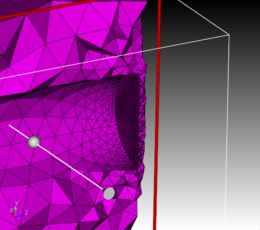
Figure 2. Demonstrates the effect of using proximity layers on a cut-away section of a volume. Note the layers of smaller tets placed in the thin region.
Geometry Approximation Angle <angle>
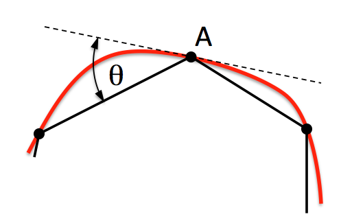
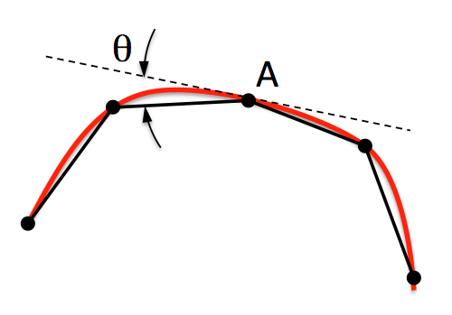
For non-planar CAD surfaces, an approximation must always be made to capture the curved features using the linear faces of the tetrahedra. When a geometry approximation angle is specified, the tet mesher will adjust element sizes on curved surfaces so that the linear edges of the tetrahedra will deviate no greater than the specified angle from the geometry. Figure 3 illustrates how the geometry approximation angle is determined. If the red curve represents the geometry and the black segments represent the mesh, the angle θ is the angle between the tangent plane at point A and the plane of a triangle at A. θ represents the maximum deviation from the geometry that the mesh will attempt to capture. As shown in figure 2(b), a smaller geometry approximation angle will normally result in more elements, but it will more closely approximate the actual geometry. The default approximation angle is 15 degrees.
 |
 |
(a) |
(b) |
Figure 3. The geometry approximation angle θ is shown as the maximum deviation between the tangent plane at A and the plane of a triangle at A.
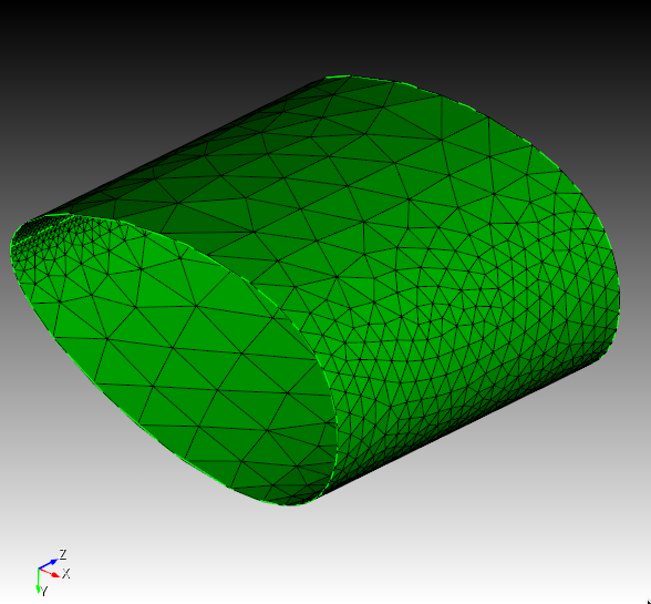
Figure 4. Demonstrates the effect of the geometry approximation angle set on the volume. Triangle sizes on the interior of surfaces will be adjusted to better capture curvature.
The user may set options that control the operation of the tet-meshing algorithms. These tetmesher options are global settings and apply to all tetmeshes generated when the scheme is set to TetMesh until the option is changed by the user.
[Set] Tetmesher Add mid_edge_nodes {on|OFF}
If the triangle mesh given to tetmeshing has quadratic (mid-edge) nodes, tetmeshing can automatically create quadratic edge nodes while generating the tets if this option has been turned on. By performing this step during tetmeshing, these nodes can be placed optimally by the Meshgems tetmesher, improving element quality. If triangle or face elements have been set to be 'respected' in the tetmesh, they must also have quadratic edge elements or meshing will fail. The default value for this option is off. If set to off, quadratic edge nodes will be placed after meshing, exactly half way along the linear edge.
[Set] Tetmesher Optimize Surface mid_edge_nodes {on|OFF}
If the triangle mesh given to tetmeshing has quadratic (mid-edge) nodes, tetmeshing can also automatically optimize the locations of these mid edges nodes during the tetmeshing operation to achieve improved quality. create quadratic edge nodes while generating the tets if this option has been turned on. By performing this step during tetmeshing, these nodes can be placed optimally by the Meshgems tetmesher, improving element quality. If triangle or face elements have been set to be 'respected' in the tetmesh, they must also have quadratic edge elements or meshing will fail. The default value for this option is off. If set to off, quadratic edge nodes will be placed after meshing, exactly half way along the linear edge.
[Set] Tetmesher Anisotropic Layers {on|OFF [<layers=2>]}
The Anisotropic Layers setting attempts to place the specified number of layers of tetrahedra through thin regions of the volume while respecting the volume mesh size in the thick direction. The default number of layers is two. This option is currently under development and can sometimes generate high aspect ratio tetrahedra. The number of layers generated can sometimes exceed the number of layers specified..
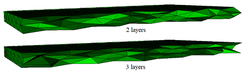
Figure 5. Anisotropic Volume Meshing
[Set] Tetmesher Boundary Recovery {on|OFF}
The TetMesh scheme includes a specialized module known as Boundary Recovery. Normally if the quality of the surface mesh is good, the boundary recovery module is not used and the resulting tet mesh will conform exactly to the triangles defined on the surfaces without additional processing. In some cases where the surface mesh contains triangles that are of poor quality (ie. highly stretched or sliver shaped triangles) the tet mesher is unable to generate sufficiently good quality elements. When this occurs, the boundary recovery module is automatically invoked. This module does additional processing to temporarily modify boundary triangles so that reasonable quality tets may be inserted. The boundary adjustment is done as an intermediate phase and in most cases the boundary triangulation remains unchanged following meshing. The TetMesh scheme in Cubit will automatically invoke the boundary recovery module if the minimum surface mesh quality drops below a condition number of 0.2. However, if the the boundary recovery option is set to ON, the tet mesher will use the boundary recovery module regardless of surface mesh quality. Turning this setting ON will normally increase the time to generate the mesh, but may result in improved mesh quality. The default setting is OFF.
[Set] Tetmesher HPC {ON|off} [Threads <value=4>]
This option turns on or off MeshGems-Tetra HPC, the multithread or distributed tetrahedral volume mesh generator. The MeshGems-Tetra HPC software is an automatic multithread or distributed tetrahedral mesh generator based on the constrained VORONOI-DELAUNAY method. Using the threads option, one can specify the maximum number of threads MeshGemsTetra HPC will use to generate the mesh. The effective number of threads used will be determined by the number of parallel subdomains used, the default of 4, and the maximum of 8. If HPC is off, the older serial tetmesher MeshGems-Tetra is used. The default setting is ON.
[Set] Tetmesher HPC minimum size [<size>]
Sets the minimum edge length in tetmeshing, when using Distene's MeshGems-Tetra HPC.
[Set] Tetmesher Interior Points {ON|off}
Infrequently, the user desires a model with as few interior points as possible. The Interior Points command allows the user to enable or disable, or turn OFF the insertion of interior points. If interior points are disabled, the tetmesher will attempt to mesh the volume using only the exterior points. This may not be possible and a few points will be inserted to allow tet-meshing to complete. The default setting is ON, meaning that interior points will be inserted according to the specified element size.
[Set] Tetmesher Optimize Level <level>
The Tetmesher Optimize Level command allows the user to control the degree of optimization used to automatically improve element quality followng the initial generation of tetrahedra. The optimization level is an integer in the range 0 to 6, which represent how aggressively the algorithm will attempt to improve element quality by automatically adjusting element connectivity and smoothing. The integers 0 to 6 can also be represented as none (0), light (1), medium (2), standard (3), strong (4), heavy (5), and extreme (6). Greater values will result in greater computation time, however may result in improved mesh quality. The default is 3 or standard optimization.
[Set] Tetmesher Optimize Overconstrained Edges {on|OFF}
This option controls the splitting of overconstrained edges. An edge is considered overconstrained when it connects two surface nodes but does not belong to the surface. This condition may not be desirable for some FEA analysis. Splitting edges can useful to guarantee two elements through the thickness. When using MeshGems-Tetra, this option cannot be used by itself; it must be used with the optimize tetrahedra option. If using MeshGems-Tetra HPC, it can be used by itself. The default for optimize overconstrained edges is OFF.
[Set] Tetmesher Optimize Overconstrained Tetrahedra {on|OFF}
In some cases, the default mesh generated with the TetMesh scheme may result in cases where more than one triangle face of a single tetrahedra lies on the same geometric surface. This condition may not be desirable for some FEA analysis. The default for optimize overconstrained tetrahedra is OFF.
[Set] Tetmesher Optimize Sliver {on|OFF}
A sliver tetrahedra is one in which the four nodes of the tet are nearly co-planar. Sliver tets are a common occurrence when using the Delaunay method, but are normally removed by standard optimization. In some cases, sliver tets may still remain even after optimization. To facilitate removal of all sliver-shaped tets, the optimize sliver option may be set to ON. In this event, additional processing will be done on the mesh to attempt to identify and remove all sliver-shaped tets from the mesh. Since this step may take additional time, and in most cases is not needed, the default setting is OFF.
[Set] Tetmesher Optimize Default
The Tetmesher Optimize Default command restores the default optimization values: level = 3 (standard), overconstrained edges = off, overconstrained tetrahedra = off, and sliver = off.
Tet meshing can be used to generate hexahedral meshes using the THex command. Each of the tetrahedron can be converted into 4 hexes, producing a fully conformal hexahedral mesh, albeit of poorer quality. These meshes can often be used in codes that are less sensitive to mesh quality and mesh directionality. The THex command requires that all tets in the model be converted to hexahedra with the same command.
In some cases it is necessary for the finite element mesh to conform to internal features of the model. The tetmesh scheme provides this capability provided the tetmesh respect command has been previously issued to define the features that will be respected.
Volume <volume_id> Tetmesh Respect {Face|Tri|Edge|Node} <range>
The tetmesh respect command allows the user to specify mesh entities that will be part of a tetrahedral mesh. These faces, triangles, edges, or nodes are inside the volume since all surface mesh features will appear in the final tetrahedral mesh by default. These mesh entities specified to be respected can be generated from other meshing commands on free vertices, curves, or surfaces.
Figure 2. Example of using tetmesh respect to ensure node 9 is captured in the tetmesh.
Figure 2 is an example of using the tetmesh respect command to enforce a node at the center of a cube. Node 9 in this example was generated by first creating a free vertex at the center location and meshing the vertex. (mesh vertex 9). The following commands would then be used to generate the tetmesh that respected node 9.
volume 1 scheme tetmesh
tetmesh respect node 9
mesh volume 1
The tetmesh respect command can also be used to enforce multiple mesh entities. To accomplish this, the tetmesh respect command may be issued multiple times. For example, If node 12 and a triangle 2 inside volume 3 was to appear in the volumetric mesh, the following commands could be used:
volume 3 scheme tetmesh
volume 3 tetmesh respect node 12
volume 3 tetmesh respect tri 2
mesh volume 1
Unlike the tetmesh respect command described above, the tetmesh respect file and tetmesh respect location commands do not require underlying geometry.
Volume <volume_id> Tetmesh Respect File '<filename>'
Volume <volume_id> Tetmesh Respect Location (options)
These two commands create mesh data that only the tetmesher knows about. Thus, to respect a point at (1.0, 0.0, -1.0) in your model, enter the command
volume 1 tetmesh respect location 1 0 -1
This is much simpler than creating the vertex, meshing it, and then respecting it.
If the model has many points that must be respected, use the file version of the command. First generate a file with all of the points, edges, and triangles that should be respected. The format of the file is the format used by the facet file. Now, use the following command to respect all of the information in the file for the given volume.
volume 2 tetmesh respect file 'my_points.facet'
Finally, the following command is used to remove the respected data from an entity.
Volume <volume_id> Tetmesh Respect Clear
The tetmesh respect clear command is the only way to remove respected data from a volume without deleting the volume. Unfortunately, it removes all respected data from the volume. Therefore, if the model has a lot of data to be respected, it is best to put it in a file or keep a journal file that can be edited.
Volume <id_range> Tetmesh growth_factor <value 1.0 to 10.0 = 1.05>
The growth_factor option controls how fast the tetrahedra sizes can change when transitioning from small to larger sizes within the volume. For example a value of 1.5 will attempt to limit the ratio between 2 adjacent tetrahedral edges. Valid values for gradation should be greater than or equal to 1.0 and usually less than 2 or 3. The larger the value, the faster the transition is. Likewise, values closer to 1.0 will result in a more uniform mesh. The default setting for growth_factor is 1.05, allowing for a somewhat slow transition between sizes within a volume. The size at the interior of a volume can be controlled using the Volume <range> [Interval] Size <interval_size> command.
Gradation of the triangles on the surfaces can also be controlled independently using the global settings [set] trimesher surface gradation and [set] trimesher volume gradation.
Tetmesh Tri <ids> [growth_factor <value>] [Make {Block|Group} [<id>]]
Tetmesh Tri <ids> [growth_factor <value>] {Add|Replace} {Block <id>|Group <id>}
The Tetmesh Tri command generates a tetrahedral mesh from the list of triangles entered. The triangles must form a closed surface. The command fails if they do not. The list of triangles may be a skin, and thus a command such as tetmesh tri in block 1 would be acceptable, should block 1 be a previously defined skin.
The first command form has optional arguments. If the make option and its arguments are present, then the specified block or group will contain the generated tet elements. The command fails with the make option if the specified block or group already exists. If the block or group id is omitted, the next available block or group id is used.
The second command form has two options, add and replace. Each option requires specifying an existing block or group. If the block or group does not exist, the command fails. The add option appends the tet elements to the block or group. The replace option removes any existing mesh from the block or group before adding the tet elements.
The growth_factor option helps control the transition from small to larger sizes within the mesh. The value specified will be the approximate ratio in the size of adjacent tets going from the boundary into the interior of the mesh. For example, a growth_factor of 1.0 will give near-constant sizing, while a growth_factor of 1.3 allows approximately 30% growth in each layer of adjacent tets.