Cubit 16.02 User Documentation
The Reduce Bolt command is intended to prepare a volume identified as a bolt for analysis by simplifying its geometry, fitting to overlapping geometry, creating blocks and groups, etc. For the core option of the reduce command, a cylindrical geometry surrounding the bolt will be webcut from the surrounding geometry. The core geometry is often used to define a higher resolution hex mesh than the surrounding geometry to better capture potential failure conditions. The core option can also manage corresponding "insert" volumes surrounding the shaft of the bolt. The reduce bolt core command is similar to the reduce bolt fit_volume command except that the core option adds the ability to define a core region surrounding the bolt.
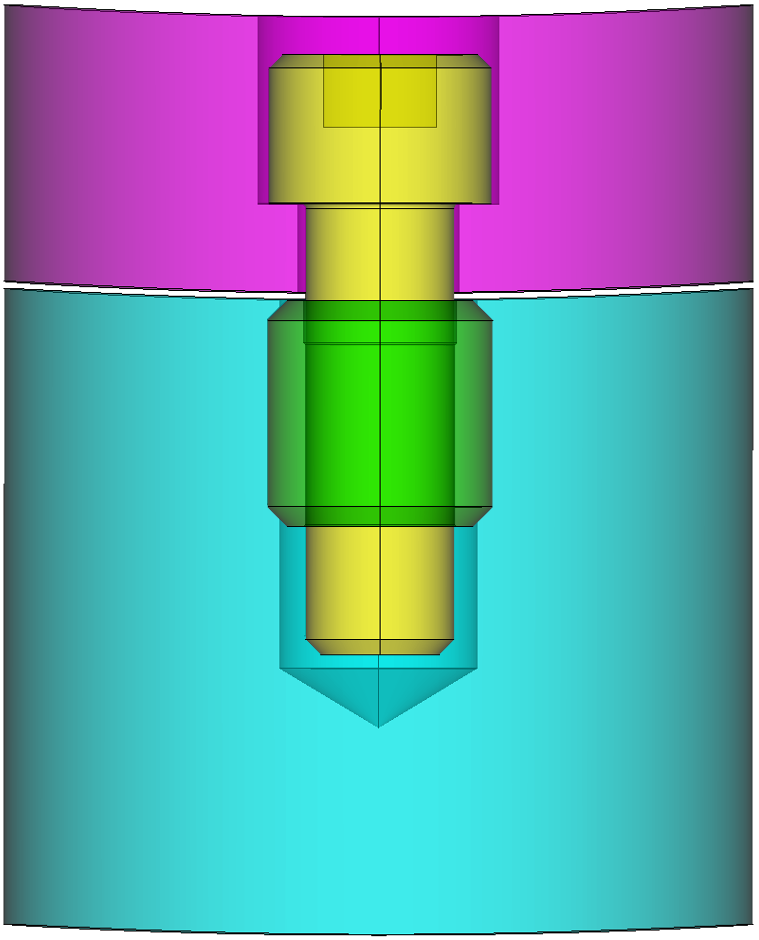
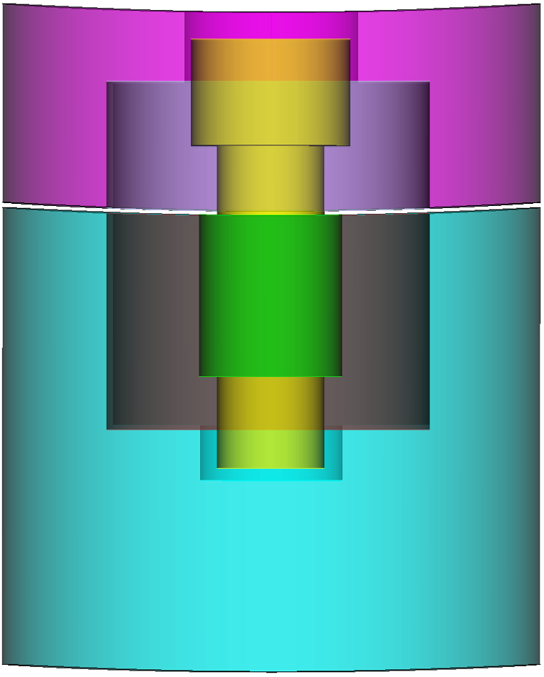
Figure 1. Example before and after of the Reduce Bolt Core command
Syntax:
Reduce volume {<ids>} bolt core
[insert volume {<ids>}] [c1 <value>] [c2 <value>] [c3 <value>] [diameter {<value>|auto}] [align_axis] [tight_fit] [adjust_hole_diameter] [simplify_hole] [remove_key] [merge] [webcut [{Head|Shank|BOTH}]] [mesh] [mesh_size <value>] [bolt_block_id {<value>|Default}] [bolt_block_name {<string>|Default}] [increment_bolt_block_id] [head_block_id {<value>|Default}] [head_block_name {<string>|Default}] [increment_head_block_id] [shank_block_id {<value>|Default}] [shank_block_name {<string>|Default}] [increment_shank_block_id] [plug_block_id {<value>|Default}] [plug_block_name {<string>|Default}] [increment_plug_block_id] [insert_block_id {<value>|Default}] [insert_block_name {<string>|Default}] [increment_insert_block_id] [core_top_block_id {<value>|Default}] [core_top_block_name {<string>|Default}] [increment_bolt_core_top_id] [core_bottom_block_id {<value>|Default}] [core_bottom_block_name {<string>|Default}] [increment_core_bottom_block_id] [preview]
Discussion:
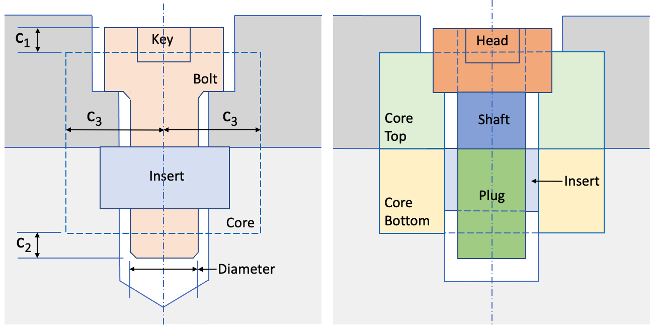
The dimensions of the core geometry are defined relative to the bolt that it surrounds. Two core volumes are normally generated where the cylindrical core geometry is subtracted from the top and bottom volumes as illustrated in figure 1. In addition to generating the core volumes, the bolt can be automatically webcut into three parts: head, shank and plug. If an insert volume is present, it can be automatically modified to remove overlap and merged to the shank and hole surfaces. In addition the diameter of the bolt shank can be altered, the hole fit to the shank diameter and the the allen key cavity optionally removed. The resulting volumes can in turn be hex meshed and assigned to blocks.
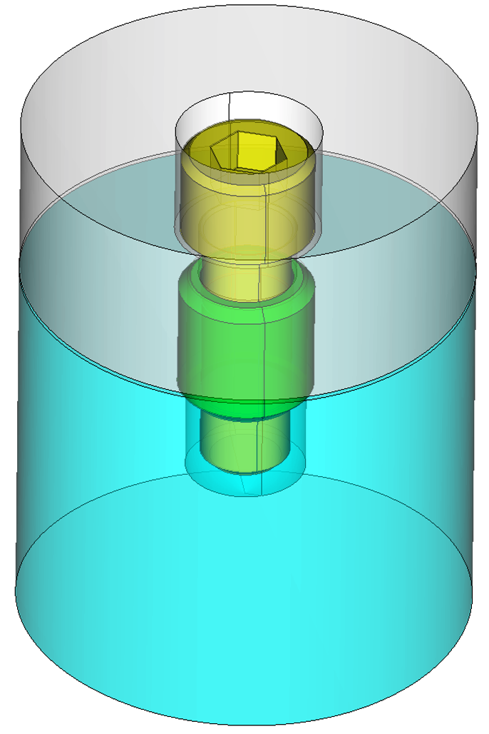
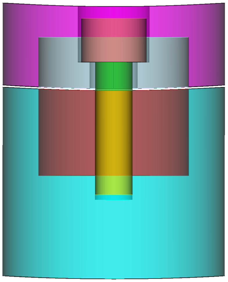
An example of the reduce bolt core operation is illustrated in figures 2 and 3. In this example, an "insert" volume is present that is overlapping the hole geometry. The resulting geometry from the operation is shown in figure 3.
Figure 2. Bolt and insert geometry prior to reduce bolt core operation showing nearby volumes. |
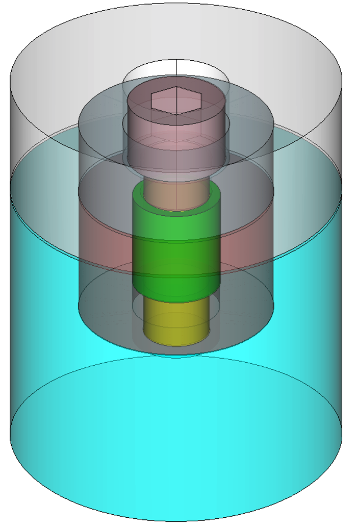
Figure 3. Bolt, insert and core volumes after the reduce operation |
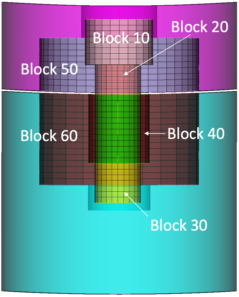
The reduce bolt core operation also provides the option to assign the resulting volumes to blocks and mesh the volumes at a specified size. Figure 4 illustrates the resulting default blocks and mesh denerated from the example shown in figure 3.
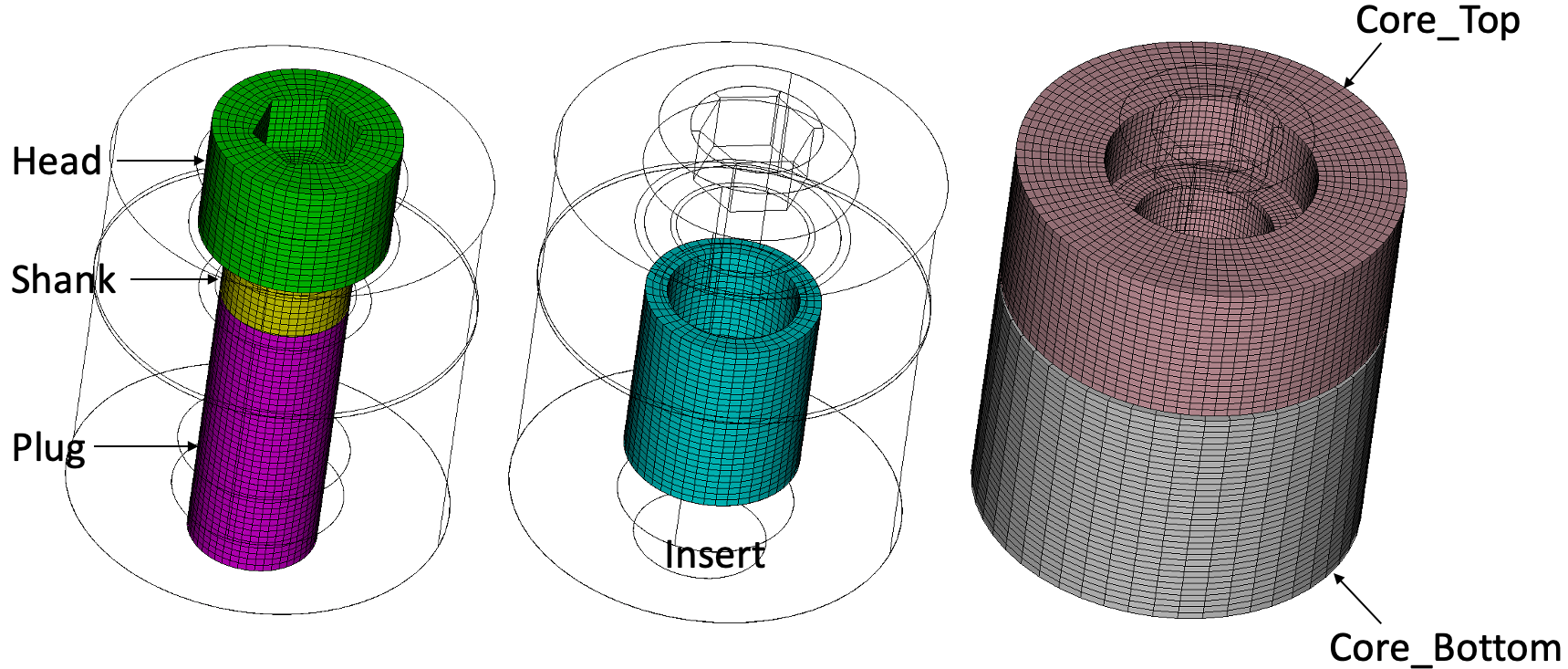
Figure 4. Example blocks and mesh automatically generated from the Reduce Bolt Core command
The following outlines the options for the reduce bolt fit_volume command.
volume ids: Specify the ids of the volumes to be reduced. The Geometry Power Tool classification diagnosic can be used for identifying volumes as "bolts".
insert {volume <ids>}: An insert is a cylindrical shaped volume which may be surrounding the shaft of the bolt. The top of the insert is usually flush with the lower volume (light grey volume in figure 1). When using the insert option with the ID of the insert volume, the reduce command will automatically simplify the insert geometry, removing any fillets, rounds or small features on the insert. Any overlap or gap between the shaft and surrounding geometry will be removed so that the insert will fit flush with the shaft and bolt hole. The tight_fit and adjust_hole_diameter options cannot be used when including an insert. If the insert option is not used, any existing insert geometry that may be present at the bolt shaft will be ignored.
c1 <value>, c2 <value>, c3 <value>: Dimensions relative to the bolt defining the size of the core geometry as illustrated in Figure 1.
diameter {<value>|auto}: Use the diameter option to alter the diameter of the bolt shank to a specific diameter indicated by <value>. The auto option will change the diameter of the bolt to exactly match the diameter of its hole. If the diameter option is not used, the existing diameter of the bolt will be used.
align_axis: Use this option if the center line of the bolt does not exactly match its hole center line. This option will automatically transform and rotate the bolt volume so that the center line of the hole and bolt are aligned and the bolt head is in contact with the upper volume.
tight_fit: This option is normally used when the bolt shaft is overlapping the lower geometry as shown in figure 2. The tight_fit option will perform a boolean subtract operation to ensure that the bolt exactly fits the shaft geometry to the lower volume, removing any gaps and overlaps surrounding or below the bolt. Figure 3 shows the result of the tight_fit option. This option cannot be used if an insert volume is also specified. See figure 4. for an example illustrating the tight_fit option.
adjust_hole_diameter: This option is normally used to adjust the diameter of the surrounding hole to match that of the bolt shaft, removing any gap or overlap. In contrast to the tight_fit option, only the hole diameter is tweaked without removing any existing void space below the bolt. This option cannot be used if an insert volume is also specified. See figure 4 for an example illustrating the the adjust_hole_diameter option.
simplify_hole: Bolt holes can sometimes include a fillet at the lip of the hole and/or a conical shape indentation at its base. The simplify_hole option will automatically remove these features from the hole leaving a flat base and sharp corner at the lip. Simplify_hole is usually used with the adjust_hole_diameter to ensure the shank fits flush with the hole surfaces and the hole is simplified. Simplify_hole has no effect on the lower volume if the tight_fit option is used. It can however simplify the upper volume if it contains any fillets or chamfers at its lip.
remove_key: The bolt geometry can often include a hexagonal shaped hole at the top of the bolt that fits an allen key. By default, this key hole will not be removed. Including the remove_key will ensure this hole is removed from the bolt geometry. If the mesh option is used, a hex mesh can be generated in most cases either with or without the key removed. Hex meshing will most likely be unsuccessful if the diameter of the key hole exceeds that of the bolt shaft. As a consequence, remove_key option may be necessary to facilitate meshing.
webcut [{Head|Shank|BOTH}]: The bolt can be cut into up to 3 different volumes as shown in figure 1. Using the optional Head or Shank options a single webcut can be executed separating just the head from the shank or just the shank from the plug respectively. If no arguments are used to the webcut option, or the both option is used, both webcuts will be performed resulting in three volumes. The location of the webcut on the shank will be where the bolt exits the lower volume.
merge: When the merge option is used. the plug portion of the bolt will be imprinted and merged with the hole surface(s) in the lower volume. In addition, the plug, shaft and head will be merged together. If an insert volume is specified, the exterior insert surface will be imprinted and merged with the hole surface(s) and the bolt plug will be imprinted and merged with the interior surface(s) of the insert. If the merge option is not used, all volumes created from the reduce command will not be imprinted or merged.
mesh: This option will attempt to generate a swept mesh on the bolt and insert geometries as part of the reduce command. If the allen key hole is present in the bolt head, a webcut will be performed on the bolt geometry to facilitate meshing. If meshing is unsuccessful, consider using the remove_key option.
mesh_size <value>: Specifies the mesh size to be used with the mesh option. If not specified, an automatic size will be determined.
Block ID and name assignment:When the webcut option is used, the resulting volumes may be assigned to a block. The following options may be used to assign to blocks based on an ID or a block name:
If webcut is not used, the resulting reduced bolt volume may still be assigned to a block id using either the bolt_block_id {<value>|Default} or bolt_block_name {<string>|Default} options.
Each of the block ID specifications for bolt, plug, shaft and head also have a corresponding optional increment argument. When assigning new webcut volumes to blocks, the block ID can be automatically generated by incrementing from a specified block_id. For example, if head_block_id is defined as 100, and the increment_head_block_ids option is used, each new head volume generated will be assigned to a new unique block id starting with 100, followed by 101, 102, 103, etc.
If an insert volume is specified, insert_block_id, insert_block_name and increment_insert_block_id may also be used in a similar manner to set up block information on the insert volume.
preview: optional argument to display a preview of the reduce bolt fit_volume operation without execution of the reduction. This option will display the reduced bolt geometry in blue with the surrounding volumes displayed in wireframe.
The following figures illustrate variations on the core option for the reduce bolt command.
(a) |
(b) |
Initial CAD geometry |
reduce volume 2 bolt core insert volume 1 c1 0.936345 c2 0.936345 c3 3.4749 simplify_hole remove_key merge |
(c) |
(d) |
reduce volume 2 bolt core c1 1 c2 1 c3 4 diameter 2 adjust_hole_diameter simplify_hole remove_key webcut merge |
reduce volume 2 bolt core insert volume 1 c1 1 c2 1 c3 4 diameter 2 simplify_hole remove_key webcut merge mesh mesh_size 0.3 head_block_ID 10 shank_block_ID 20 plug_block_ID 30 insert_block_ID 40 core_top_block_ID 50 core_bottom_block_ID 60 |
Figure 5. Examples of using the reduce bolt core command where (a) is the original geometry. In (b), an insert volume is included and the dimensions of the core are specified. Figure (c) does not include the insert and modifies the dimensions of core using the c1, c2 and c3 options. In addition, the diameter of the bolt shaft has been modified from its original diameter and the bolt cut into head, shank and plug volumes. Figure (d) again includes the insert and also specifies a mesh and custom mesh size to be used. In addition, note that block IDs for each of the resulting volumes have been specified. The resulting block IDs are also illustrated in figure (d).