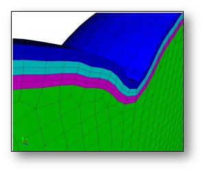
Example of boundary layers.
Cubit 15.9 User Documentation
Sculpt options for defining boundary layers in the mesh. Boundary layers are thin hex layers that can be defined at surfaces, extending either inward or outward from a material. The user may specify the number and thickness of the hex layers as well as the material ID of the layers. Layer thicknesses should normally be "thin" with respect to the size of the cells. Layers will not intersect, so should be defined on surfaces where nearby layers will not overlap. Boundary layers are specified based upon a material ID, where hex layers will be placed at surfaces where the material interfaces with other materials, or at free surfaces.
Example of boundary layers.
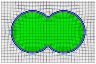
Boundary layers defined at the surfaces of a material.
Boundary Layers              -bly     --boundary_layer
  --begin                    -beg  <arg> Begin specification blayer or blayer_block
  --end                      -zzz  <arg> End specification blayer or blayer_block
  --material                 -mat  <arg> Boundary layer material specification
  --num_elem_layers          -nel  <arg> Number of element layers in blayer block
  --thickness                -th   <arg> Thickness of first element layer in block
  --bias                     -bi   <arg> Bias of element thicknesses in blayer block

Sculpt Command Summary
Command: begin     Begin specification blayer or blayer_block

Input file command:   begin <arg>
Command line options: -beg <arg>
Argument Type:        blayer, blayer_block
Command Description:
Defines the beginning of a specification block. Must be closed with "end" argument. Currently supports the following specifications:
blayer
Defines a boundary layer specification. Layers of hex elements are
placed at the interface of a given material. Valid argumnts used within
a blayer specification include: material, and begin blayer_block.
blayer_block
Defines a set of element layers within a given blayer definition that
share a common material ID. Valid arguments used within a blayer_block
specification include: material, num_elem_layers, thickness and bias.
Example:
The following example shows a boundary layer specification in a sculpt
input file. In this example, two boundary layer blocks are defined at
the interface of materials 1 and 2. Two material blocks with ID 3 and 4 are
generated with 1 and 2 element layers respectively.
       BEGIN BLAYER
         MATERIAL = 1 2
         BEGIN BLAYER_BLOCK
           MATERIAL = 3
           NUM_ELEM_LAYERS = 1
           THICKNESS = 0.1
         END BLAYER_BLOCK
         BEGIN BLAYER_BLOCK
           MATERIAL = 4
           NUM_ELEM_LAYERS = 2
           THICKNESS = 0.2
           BIAS = 1.3
         END BLAYER_BLOCK
       END BLAYER
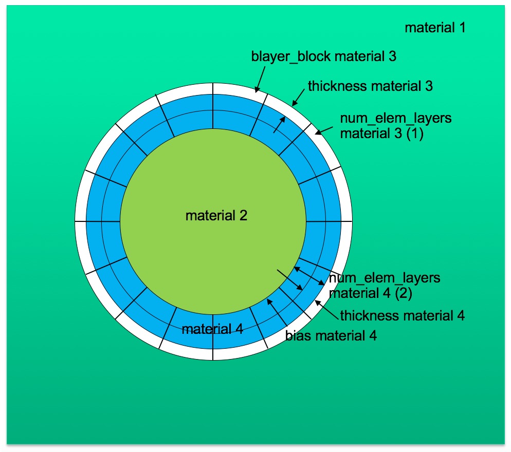
Example schema for boundary layers corresponding to input file below.
Command: end     End specification blayer or blayer_block

Input file command:   end <arg>
Command line options: -zzz <arg>
Argument Type:        blayer, blayer_block
Command Description:
Defines the end of a specification block. Must be preceded with "begin" argument. Currently supports arguments blayer and blayer_block.
Command: material     Boundary layer material specification

Input file command:   material <arg>
Command line options: -mat <arg>
Argument Type:        integer > 0
Command Description:
Defines a material ID in a boundary layer specification. When used within a BLAYER specification, it references one or two existing materials in the input where boundary layers will be generated. If a single material is specified, hex layers will be generated at all interfaces of the designated material with any adjacent material. If two material IDs are specified, layers will be generated only at interfaces where the two materials are adjacent.
In most cases, the material ID(s) in the BLAYER specification refer to material IDs defined in the diatom file for specific geometry inserts such as STL files or diatom primitives. It can also be defined as the void material ID (VOID_MAT) or a material in a volume fraction description such as input_vfrac, input_micro, input_cart_exo or input_spn.
When used within a BLAYER_BLOCK specification, it refers to a new block that will be generated for which all elements in the blayer_block will be assigned. Normally it refers to a unique material ID that is not already referenced in the input. Where the material ID is already used, elements in the blayer block will be added to the existing material.
A material ID must be defined for both a BLAYER and BLAYER_BLOCK. This value does not have a default.
Command: num_elem_layers     Number of element layers in blayer block

Input file command:   num_elem_layers <arg>
Command line options: -nel <arg>
Argument Type:        integer > 0
Command Description:
Number of element layers to be defined within a BLAYER_BLOCK specification. num_elem_layers must be defined for all BLAYER_BLOCKs.
Command: thickness     Thickness of first element layer in block

Input file command:   thickness <arg>
Command line options: -th <arg>
Argument Type:        floating point value
Command Description:
Thickness of the first layer defined in a BLAYER_BLOCK. Value is an absolute distance. No default is provided and must be defined for all BLAYER_BLOCKs
Command: bias     Bias of element thicknesses in blayer block

Input file command:   bias <arg>
Command line options: -bi <arg>
Argument Type:        floating point value
Command Description:
Bias factor applied to additional layers of a BLAYER_BLOCK. Used in conjunction with the THICKNESS parameter (thickness of first layer) it defines a multiplier for the thickness for subsequent element layers defined within the same BLAYER_BLOCK. Default BIAS is 1.0 and is optional.