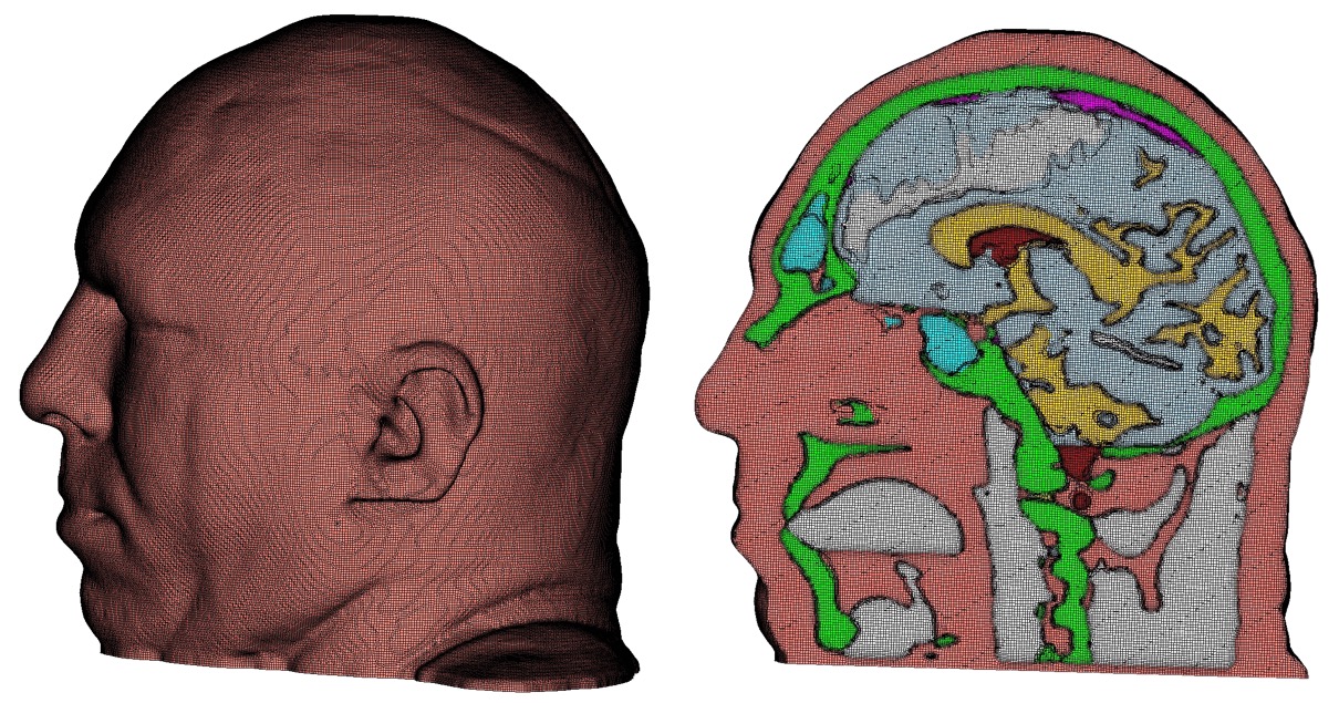
Example mesh generated with Diatom bitmap option
Cubit 15.8 User Documentation
Options for specifying input files to Sculpt. Sculpt uses a method for representing geometry based upon volume fractions defined on a Cartesian or unstructured grid. Sculpt will accept facet-based (STL) or analytic (diatom) geometry, but will first convert the input geometry to the required volume fraction description before generating the hexahedral mesh. Various formats for volume fraction data can also be imported directly into Sculpt and used as the basis for hex meshing. The following formats for geometry are currently supported in Sculpt:
Input Data Files             -inp     --input
  --stl_file                 -stl <arg> Input STL file
  --diatom_file              -d   <arg> Input Diatom description file
  --input_vfrac              -ivf <arg> Input from Volume Fraction file base name
  --input_micro              -ims <arg> Input from Microstructure file
  --input_cart_exo           -ice <arg> Input from Cartesian Exodus file
  --input_spn                -isp <arg> Input from Microstructure spn file
  --spn_xyz_order            -spo <arg> Ordering of cells in spn file
  --lattice                  -l   <arg> STL Lattice Template File

Sculpt Command Summary
Command: stl_file     Input STL file

Input file command:   stl_file <arg>
Command line options: -stl <arg>
Argument Type:        file name with path
Command Description:
File name of a single STL (facet geometry) file to be used as input. Either an stl_file or diatom_file designation should be included to run Sculpt. The stl_file option will support a single STL file. To use multiple STL files, where each file represents a different material, use the diatom_file file option where multiple file names may be specified.
It is recommended that STL files used as input to Sculpt be "water-tight". While in many cases non-watertight geometries will be successful, unexpected or incorrect results may result. It is recommended practice to use Cubit to first import the STL geometry and allow the sculpt parallel command to write a new STL geometry file for use in Sculpt. Cubit's sculpt parallel command will attempt to stitch and repair any triangle facets that are not completely closed. Other commercial tools are available for STL geometry that may be effective in repairing the geometry prior to use in Sculpt.
Command: diatom_file     Input Diatom description file

Input file command:   diatom_file <arg>
Command line options: -d <arg>
Argument Type:        file name with path
Command Description:
File name of a diatom file to be used as input to Sculpt. Both stl_file and diatom_file cannot be used simultaneously. A diatom file is a constructive solid geometry description containing primitives for generating a full geometric definition of the model. Diatoms are commonly used as input to Sandia's CTH and Alegra codes. Multiple STL files can also be defined in a Diatom file. The following is a simple example of a diatom file that would read 3 different STL files:
    diatoms
      package 'blue_material'
        material 1
        insert stl
          file = 'blue_part1.stl'
        endinsert
        insert stl
          file = 'blue_part2.stl'
        endinsert
      endpackage
      package 'red_material'
        material 2
        insert stl
          file = 'red_part1.stl'
        endinsert
      endpackage
    enddiatom
Note that the first two files, blue_part1.stl and blue_part2.stl belong to the
same material. As a result, elements generated within the geometry of these
files will belong to block 1. Likewise, the elements generated within the
geometry of red_part1.stl will belong to block 2.
Bitmap Files
The Diatom format will also support bitmap files. These are binary files that set each cell either on or off for the specified material. The following is an example diatom specification for a bitmap file. Note that the bitmap specification includes nx, ny, nz dimensions for the size of the input file.
    diatoms
      package 'Skull'
        material 1
        insert bitmap
          file = 'skull_bitmap_file'
          nx = 680
          ny = 408
          nz = 236
        endinsert
      endpackage
    enddiatom
Example mesh generated with Diatom bitmap option
For a full description of the diatom format see the CTH or Alegra documentation.
D. A. Crawford, A. L. Brundage, E. N. Harstad, K. Ruggirello, R. G. Schmitt, S. C. Schumacher and J. S. Simmons, "CTH User’s Manual and Input Instructions, Version 10.3", CTH Development Project, Sandia National Laboratories, Albuquerque, New Mexico 87185, February 14, 2013
Command: input_vfrac     Input from Volume Fraction file base name

Input file command:   input_vfrac <arg>
Command line options: -ivf <arg>
Argument Type:        base file name with path
Command Description:
Sculpt can optionally take an exodus file containing volume fraction data stored as element variables. Normally the exodus file has initially been written using the --volfrac_file (-vf) option. Since the exodus file will be a Cartesian grid spread across multiple processors, the base filename for the parallel series of exodus files is used as the argument for this command. The input volume fraction file(s) would be used instead of an STL or diatom file. Since computing volume fractions from geometry can be time consuming, precomputing the volume fractions and reading them from a file can be advantageous if multiple meshes are to be generated from the same volume fraction data.
Command: input_micro     Input from Microstructure file

Input file command:   input_micro <arg>
Command line options: -ims <arg>
Argument Type:        file name with path
Command Description:
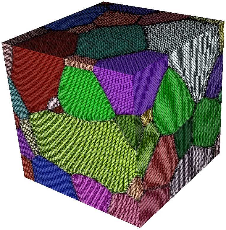
Example all-hex mesh of microstructure
A microstructure file is an ascii text file containing volume fraction data for each cell of a Cartesian grid. The format for this file includes header information followed by data for each cell. The following is an example:
TITLE = triple line system
VARIABLES = x y z, phi_1, phi_2, phi_3
ZONE i = 2 , j = 2 , k = 2
0.0000       0.0000       0.0000      0.5000      0.5000      0.0000
1.0000       0.0000       0.0000      0.3333      0.3333      0.3334
0.0000       1.0000       0.0000      1.0000      0.0000      0.0000
1.0000       1.0000       0.0000      0.0000      1.0000      0.0000
0.0000       0.0000       1.0000      0.2000      0.4000      0.4000
1.0000       0.0000       1.0000      0.6000      0.1000      0.3000
0.0000       1.0000       1.0000      0.0000      0.0000      1.0000
1.0000       1.0000       1.0000      0.9000      0.0000      0.1000
The header information should contain the following:
TITLE: any descriptive character string
VARIABLES: a list of variables separated by spaces or commas. It should include x, y, z as the first three variable names. The remaining names are arbitrary. The number of variable names listed must correspond to the number of data values for each cell of the Cartesian grid.
ZONE: Specify the number of cells in the i, j and k directions (corresponding to x, y, and z respectively)
The body of the file will contain one line per cell of the grid. The first three values correspond to the centroid location of a cell in the grid. The remaining values represent volume fractions for the cell for each variable listed. The sum of the volume fractions for each individual cell should be 1.0
Currently this format assumes that cell sizes are exactly 1.0 x 1.0 x 1.0 and the minimum cell centroid location is always 0.0, 0.0, 0.0. This results in a Cartesian grid with minimum coordinate = (-0.5, -0.5, -0.5) and maximum coordinate = (i-0.5, j-0.5, k-0.5). If a size other than 1x1x1 is required consider using the scale and/or translate options.
Example usage of this command is as follows:
sculpt -j 8 -ims my_micro_file.tec -p 1
Smoothing: Sculpt will set automatic defaults for smoothing if user options have not been defined. These include:
--smooth 9 (surface smoothing option - no surface projection)
--csmooth 2 (curve smoothing option - hermite interpolation)
These options will generally provide a smoother curve and surface representation but may not adhere strictly to the volume fraction geometric definition. To over-ride the defaults, consider using the following options:
--smooth 8 (surface smoothing option - projection to interpolated surface)
--csmooth 5 (curve smoothing option - projection to interpolated curve)
Pillowing: For most 3D models it is recommended using pillowing since triple junctions (curves with at least 3 adjacent materials) will typically be defined where malformed hex elements would otherwise be generated. Surface pillowing (option 1) is usually sufficient to remove poor quality elements at triple junctions.
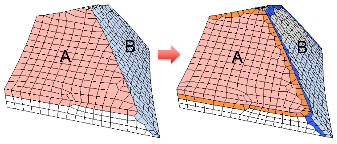
Pillows (hex layers) inserted at surfaces to improve element quality around curves. Note mesh quality at curve between surfaces A and B.
Command: input_cart_exo     Input from Cartesian Exodus file

Input file command:   input_cart_exo <arg>
Command line options: -ice <arg>
Argument Type:        file name with path
Command Description: An exodus mesh containing a Cartesian grid of elements can also be used as the source of a sculpt mesh. For this option the following conditions must be met:
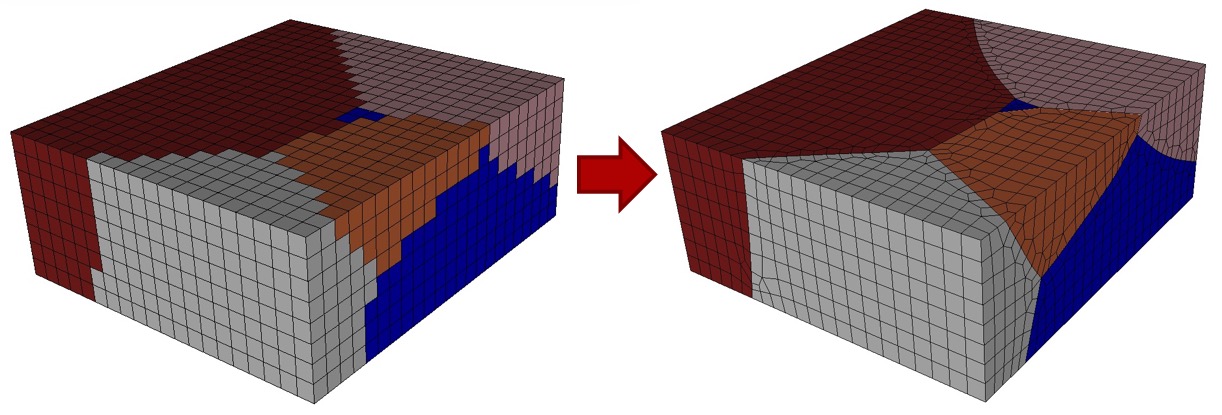
Example Cartesian Exodus file and the resulting hex mesh.
Provided these conditions are met, sculpt will treat each block as a separate material and generate a smooth conforming mesh between the materials. This option is useful for converting a stair-step mesh into a smooth conforming mesh. The resulting sculpt mesh will have the same dimensions as the original exodus mesh, but will add layers of hexes at material interfaces.
Example usage of this command is as follows:
sculpt -j 8 -ice my_cartesian_file.e -p 1
Smoothing: Sculpt will set automatic defaults for smoothing if user options have not been defined. These include
--smooth 9 (surface smoothing option - no surface projection)
--csmooth 2 (curve smoothing option - hermite interpolation)
These options will generally provide a smoother curve and surface representation but may not adhere strictly to the volume fraction geometric definition. To over-ride the defaults, consider using the following options:
--smooth 8 (surface smoothing option - projection to interpolated surface)
--csmooth 5 (curve smoothing option - projection to interpolated curve)
Pillowing: For most 3D models it is recommended using pillowing since triple junctions (curves with at least 3 adjacent materials) will typically be defined where malformed hex elements would otherwise be generated. Surface pillowing (option 1) is usually sufficient to remove poor quality elements at triple junctions.
Command: input_spn     Input from Microstructure spn file

Input file command:   input_spn <arg>
Command line options: -isp <arg>
Argument Type:        file name with path
Command Description:
A .spn file is an optional method for importing volume fraction data into sculpt for meshing. This format is a simple ascii text file containing one integer per cell of a Cartesian grid. Each integer represents a unique material identifier. Any number of materials may be used, however for practical purposes, the number of unique materials should not exceed more than about 50 for reasonable performance.
An example file containing a 3 x 3 x 3 grid with 2 materials may be defined as follows:
    1 1 2 1 2 1 1 1 1
    1 2 2 1 2 2 1 1 2
    2 1 1 1 2 1 1 2 2
Any unique integer may be used to identify a material. All cells with the same ID will be defined as a continuous block with the same exodus block ID in the final mesh. All integers should be separated by a space or newline. The number of integers in the file should exactly correspond to the size of the Cartesian grid. The dimensions of the Cartesian grid must be specified on the command line as part of the input. The following is an example:
sculpt -j 8 -x 10 -y 24 -z 15 -isp "my_spn_file.spn" -p 1
The default order of the cells in the input file will be read according to the
following schema:
    for (i=0; i<nx; i++)
      for (j=0; j<ny; j++)
        for (k=0; k<nz; k++)
           // read next value from file
Where nx, ny, nz are the number of cells in each Cartesian direction. This ordering can be changed to nz, ny, nx using the spn_xyz_order option. The initial size of the Cartesian grid will be exactly nx X ny X nz with the minimum coordinate at (0.0, 0.0, 0.0). If a size other than the default is required, consider using the scale and/or translate options.
Smoothing: Sculpt will set automatic defaults for smoothing if user options have not been defined. These include:
--smooth 9 (surface smoothing option - no surface projection)
--csmooth 2 (curve smoothing option - hermite interpolation)
These options will generally provide a smoother curve and surface representation but may not adhere strictly to the volume fraction geometric definition. To over-ride the defaults, consider using the following options:
--smooth 8 (surface smoothing option - projection to interpolated surface)
--csmooth 5 (curve smoothing option - projection to interpolated curve)
Pillowing: For most 3D models it is recommended using pillowing since triple junctions (curves with at least 3 adjacent materials) will typically be defined where malformed hex elements would otherwise be generated. Surface pillowing (option 1) is usually sufficient to remove poor quality elements at triple junctions.
Command: spn_xyz_order     Ordering of cells in spn file

Input file command:   spn_xyz_order <arg>
Command line options: -spo <arg>
Argument Type:        integer (0 to 5)
Input arguments: xyz (0)
                 xzy (1)
                 yxz (2)
                 yzx (3)
                 zxy (4)
                 zyx (5)
Command Description:
This option is valid with the 'input_spn' option. The default order of the cells in the spn input file will be read according to the following schema:
    for (i=0; i<nx; i++)
      for (j=0; j<ny; j++)
        for (k=0; k<nz; k++)
           // read next value from file
If the spn file has the cells in a different order, use this option to
specify the order. 0 (xyz) is the default.
Command: lattice     STL Lattice Template File

Input file command:   lattice <arg>
Command line options: -l <arg>
Argument Type:        file name with path
Command Description:
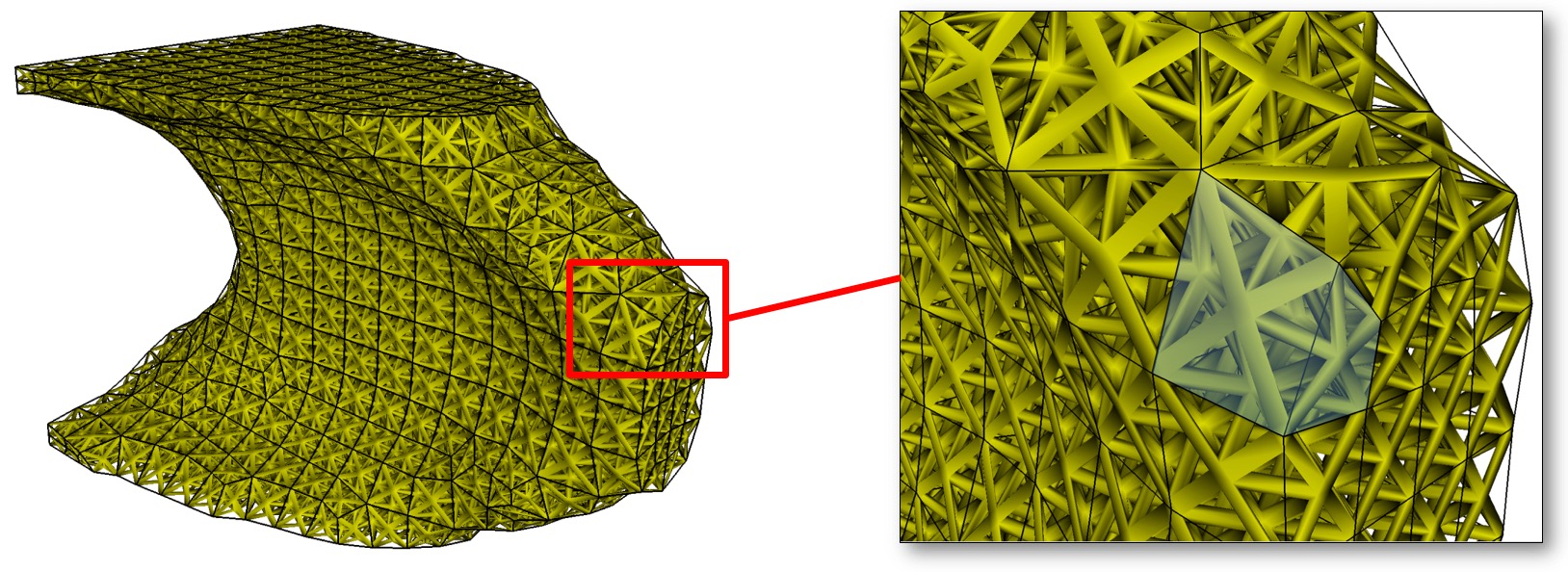
Lattice geometry generated from exodus mesh.
Generate a lattice structure from a hex mesh. This command takes the name of an STL format template file which defines the lattice over a unit cube. To generate a valid lattice structure, the facets should be symmetric to the three coordinate planes. The lattice structure will be transformed and copied into each hex of the mesh. The result will be an STL file containing lattice geometry for the mesh.
This option currently requires the name of an exodus mesh on which to define the lattice. Use the --exodus_file (-e) option to specify its path. The current implementation is limited to one block, however if a second block is contained in the Exodus file it will be treated as a solid and stl facets will be generated at the skin of the block.
The name of the output STL file may also be defined by using the --stl_file (-stl) option. If no stl file is specified, the output will use the name of the input exodus file with the extension "_lattice.stl" appended.
In addition to the full lattice geometry, an additional file containing only the lattice from the first layer of hexes will be written. This may be useful in reducing the size of the STL file for visualization purposes only. The name of this file will be the name of the full STL geometry file with the extension ".vis.stl" appended.
The following is an example input file using the lattice option:
  BEGIN SCULPT
    lattice = lattice_template.stl  $contains unit cube with triangles
    exodus_file = file.e $ hex mesh containing one or two element blocks
    stl_file = file.stl $ name of output stl file
  END SCULPT
Note that this option is currently limited to serial execution (-j 1)